Modular electric meter box

A meter box, modular technology, applied in the field of modular meter box, can solve the problems of inability to adjust the meter, limited space, inconvenient use, etc., and achieve the effect of simple processing, simple operation and convenient use

Inactive Publication Date: 2019-08-16
陈秀美
View PDF6 Cites 0 Cited by
  • Summary
  • Abstract
  • Description
  • Claims
  • Application Information

AI Technical Summary

Problems solved by technology

However, the box body of the meter box is an integral structure, and its internal space is limited, so it cannot be adjusted according to the number of meters, and different sizes need to be customized, which is not only inconvenient to use, but also troublesome to process

Method used


Image

  • Modular electric meter box
  • Modular electric meter box
  • Modular electric meter box

Examples


Embodiment 1

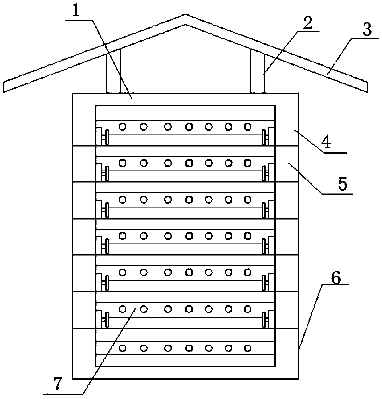
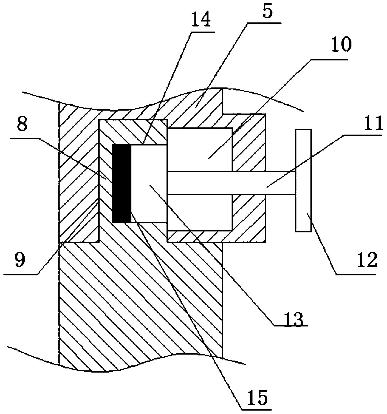
[0024] refer to Figure 1-4 , a modularized meter box in the embodiment of the present invention, comprising a meter box body 1, a door is provided on the front side of the meter box body 1, a pillar 2 is arranged on the upper end of the meter box body 1, and the upper end of the pillar 2 A rainproof cover 3 is provided, and the rainproof cover 3 is an inverted V-shaped mechanism. The meter box body 1 includes a box top 4, a box bottom 6 and a box body 5. The box body 5 is provided with several pieces, and each box body 5 Limiting projections 8 and limiting grooves 9 are respectively provided at the upper and lower ends of the upper and lower ends of the box, and the adjacent boxes 5 are connected through the cooperation of the limiting projections 8 and the limiting grooves 9, and the box body 5 is provided with a limit The buffer tank 10 connected to the bit slot 9, the buffer tank 10 is slidingly connected with a pull rod 11, the outer end of the pull rod 11 is provided wit...

Embodiment 2

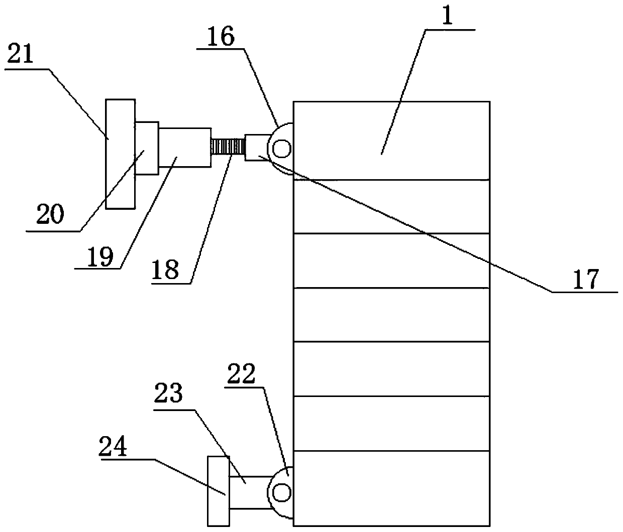
[0026] See 3 and Figure 4 , on the basis of Embodiment 1, the rear side of the box bottom 6 is symmetrically provided with a first connection seat 22, and a support column 23 is provided on the first connection seat 22, and the rear end of the support column 23 is provided with There is a first fixed plate 24, and the rear side of the box top 4 is provided with a second connecting seat 16, and a connecting block 17 is rotatably connected to the second connecting seat 16, and an adjustment mechanism is connected to the connecting block 17, so The rear end of the adjusting mechanism is connected with the second fixing plate 21 through the rotating seat 20, and the first fixing plate 24 and the second fixing plate 21 are provided with fixing holes. The adjusting mechanism includes an adjusting cylinder 19 and a threaded rod 18 , The interior of the adjustment cylinder 19 is provided with a threaded cavity that cooperates with the threaded rod 18 . It is convenient for installat...


PUM


Abstract

The invention relates to the technical field of power equipment, in particular to a modular electric meter box. The modular electric meter box comprises an electric meter box body, wherein a box dooris arranged at a front side of the electric meter box body, a strut is arranged at an upper end of the electric meter box body, a rainproof cover is arranged at an upper end of the strut, the electricmeter box body comprises a box top, a box bottom and a plurality of box bodies, a limitation convex block and a limitation groove are respectively arranged at an upper end and a lower end of each boxbody, and adjacent box bodies are connected by matching of the limitation convex block and the limitation groove. In the device structure, the electric meter box body comprises the box top, the box bottom and the box bodies, the numbers of the box bodies can be randomly increased or reduced according to the numbers of electric meters, different application demands are satisfied, the modular electric meter box is not needed to be specially customized, the modular electric meter box is convenient to use and simple to process, and the application cost is reduced.

Description

technical field [0001] The invention relates to the technical field of electric equipment, in particular to a modular electric meter box. Background technique [0002] An electric meter is an instrument used to measure electric energy, also known as an electric meter, a fire meter, an electric energy meter, and a kilowatt-hour meter, and is widely used in the electric power industry. As a terminal instrument for counting the electricity consumption of users, it is necessary to set its working environment in strict accordance with the regulations. In the area covered by the rural power grid, the electric energy meter is often installed in the outdoor electric meter box. In order to prevent the natural environment from affecting the normal operation of the meter, the meter box needs to be specially designed, such as waterproof, moisture-proof and other functions. [0003] The Chinese patent publication number is CN 108872662 A. A heat-dissipating electric meter box adopts the...

Claims


Application Information

Patent Timeline
IPC IPC(8): G01R11/04
CPCG01R11/04
Inventor 陈秀美
Owner 陈秀美
Why Eureka
Try Eureka