
Pipe cable pay-off cart

A technology for pipes, cables and carts, which is applied in the field of municipal engineering appliances, can solve the problems affecting the quality of the laying and installation progress of pipes and cables, scratches and bruises on the surfaces of pipes and cables, and injuries to operators, etc. The effect of reducing construction costs and solving inefficiencies

Pending Publication Date: 2020-06-09
JINCHUAN GROUP LIMITED
View PDF0 Cites 0 Cited by
  • Summary
  • Abstract
  • Description
  • Claims
  • Application Information

AI Technical Summary

Problems solved by technology

[0003] The existing technology manually rotates the entire tube and cable reel to lay the tube and cable. This method is time-consuming and laborious. It also requires the unloading of cranes and carts and the cooperation of multiple people to drag and drag the construction. The labor efficiency is low and it is easy to cause scratches on the surface of the tube and cable Bumps form initial damage, and there are potential safety hazards (smashing the operator), which affects the smooth progress of the quality and safety of the pipeline and cable laying installation progress

Method used


Image

  • Pipe cable pay-off cart
  • Pipe cable pay-off cart
  • Pipe cable pay-off cart

Examples


Embodiment Construction

[0025] The present invention will be described in detail below in conjunction with the accompanying drawings and specific embodiments.

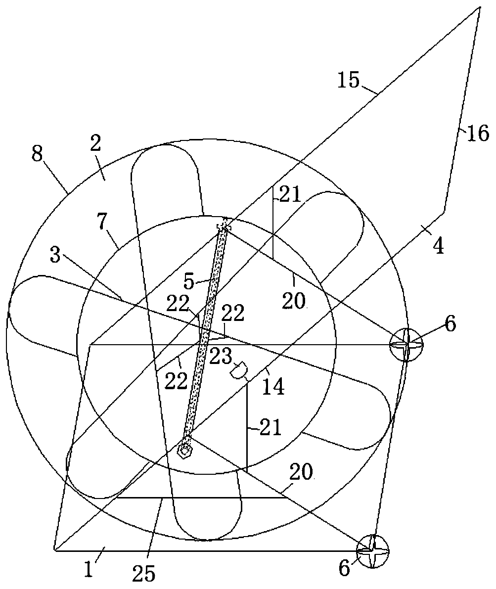
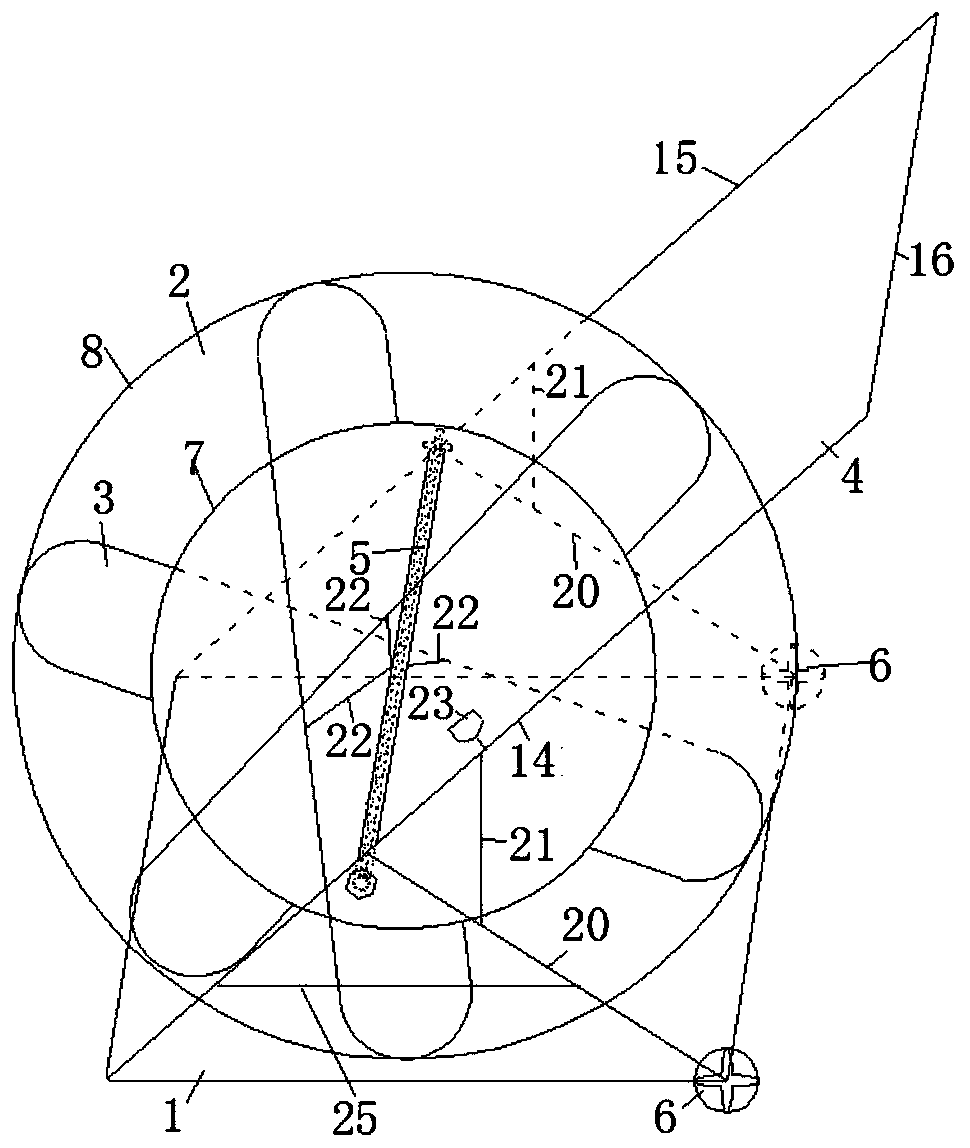
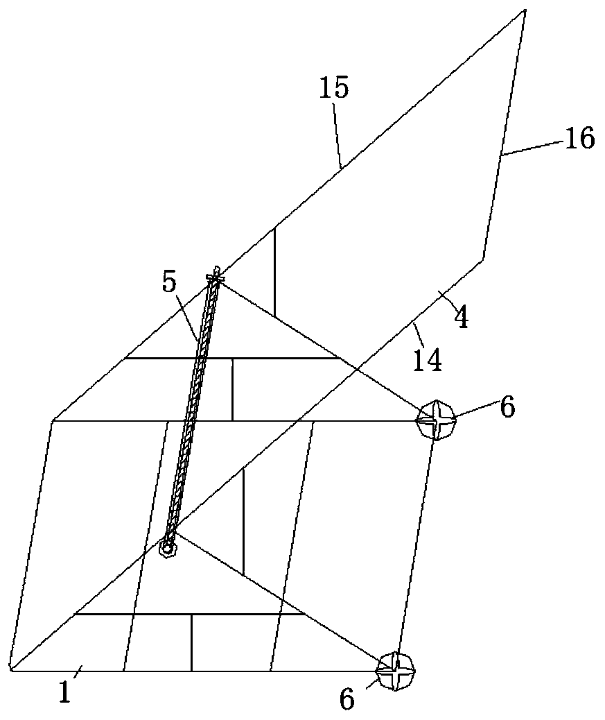
[0026] Such as Figure 1-8 As shown, a pipe and cable pay-off trolley includes: a base 1, a wire receiving frame 2, at least one wire receiving rod 3, an armrest 4, and a rotating mechanism 5;

[0027] The base 1 is a rectangular bottom frame, and a cross brace is added in the middle of the bottom frame to enhance the rigidity of the base. One end of the base 1 is provided with two spaced rollers 6, and the two rollers are respectively arranged on the two ends of the connecting beam at one end of the base 1. ;

[0028] The nanowire frame 2 comprises a first ring 7 and a second ring 8, the first ring 7 and the second ring 8 are arranged parallel to each other, the diameter of the first ring is smaller than the diameter of the second ring, the first ring and the second ring are vertically arranged, and the entire wire frame 2 is vertically ar...


PUM


Abstract

The invention discloses a pipe cable pay-off cart. The pipe cable pay-off cart comprises a base, a cable containing frame, at least one cable containing rod, a handrail and a rotating mechanism; a roller is arranged at one end of the base; the cable containing frame comprises a first circular ring and a second circular ring which are parallel to each other; the cable containing frame is verticallyarranged on the base; each cable containing rod comprises a first connecting rod, the two ends of each first connecting rod are each fixedly connected with a fixing clamp, and each fixing clamp is fixed between the outer wall of the first circular ring and the inner wall of the second circular ring; the handrail is an inverted-U-shaped rod, the inverted-U-shaped rod is obliquely arranged on the base, the bottom end of the inverted-U-shaped rod is fixedly connected with the other end of the base, a side rod on one side of the inverted-U-shaped rod is located on one side of the cable containingframe, a side rod on the other side of the inverted-U-shaped rod is located on the other side of the cable containing frame, and opposite screw holes are formed in the side rods on two sides of inverted-U-shaped rod; and the rotating mechanism is rotatably arranged between the side rods on the two sides of the inverted-U-shaped rod, and the rotating mechanism is connected with the first connecting rods through the second connecting rods. The pipe cable pay-off cart is ingenious in structural design, easy to machine and manufacture, safe and stable.

Description

technical field [0001] The invention belongs to the technical field of municipal engineering appliances, and in particular relates to a pipe and cable pay-off trolley. Background technique [0002] When the municipal engineering is laying the pipe network and cables, the whole pipe-type cable (referred to as the pipe cable) is unloaded near the wellhead pipe ditch, and the whole pipe and cable reel is manually pushed and rotated. Drag and take the pipe and cable on the ground and send it into the pipe ditch for laying. [0003] The existing technology manually rotates the entire tube and cable reel to lay the tube and cable. This method is time-consuming and laborious. It also requires the unloading of cranes and carts and the cooperation of multiple people to drag and drag the construction. The labor efficiency is low and it is easy to cause scratches on the surface of the tube and cable Bumps form initial damage, and there are potential safety hazards (injury to the opera...

Claims


Application Information

Patent Timeline
Patent Type & Authority Applications(China)
IPC IPC(8): B65H75/40B65H75/44
CPCB65H75/403B65H75/4457B65H2701/30
Inventor 李卫向段晓红
Owner JINCHUAN GROUP LIMITED
Learn More