A rotary wing elevator

A hoist and rotary wing technology, which is applied to cranes, load hanging components, electrical components, etc., can solve the problems of bracket tilt, affecting the stability of rotary wing hoists, and obstacles to hoisting and lifting of electrical equipment, so as to prevent hoisting and lifting, The effect of preventing drift and improving stability

Active Publication Date: 2022-01-07
吴红林
View PDF4 Cites 0 Cited by
  • Summary
  • Abstract
  • Description
  • Claims
  • Application Information

AI Technical Summary

Problems solved by technology

[0005] Aiming at the deficiencies in the prior art, the purpose of the present invention is to provide a rotary wing elevator to solve the problem of the prior art because the electric equipment is heavy and needs to be hoisted to a high place. When the height of the elevator is not enough, it is necessary to add a bracket at the bottom. To meet the requirements of the platform where the power equipment is to be erected, and the higher bracket is prone to tilt due to the gravity of the power equipment during hoisting and lifting, which will affect the stability of the rotor lift and hinder the hoisting and lifting of the power equipment question

Method used


Image

  • A rotary wing elevator
  • A rotary wing elevator
  • A rotary wing elevator

Examples


Embodiment 1

[0030] Example 1: Please refer to Figure 1-Figure 8 , the specific embodiments of the present invention are as follows:

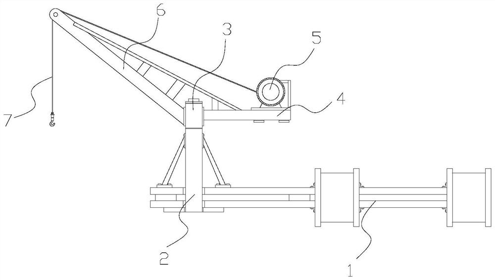
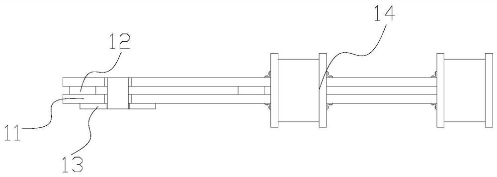
[0031] Its structure includes a mounting and fixing structure 1, a support column 2, a rotating seat 3, a bracket 4, a motor 5, a hanger 6, and a suspension cable 7. The support column 2 is vertically installed on the upper end of the installation and fixing structure 1 and is mechanically connected. The swivel base 3 is embedded and installed on the upper end of the supporting column 2 and connected by a hinge, the bracket 4 is horizontally installed on the right side of the swivel base 3 and welded, the motor 5 is fixed to the upper end of the bracket 4 by bolts, and the hanger 6 is tilted Installed on the left side of the swivel base 3, the suspension cable 7 bypasses the hanger 6 and is connected to the motor 5; A spacer 12 is connected between the frames 11, the fixed plate 13 is horizontally installed on the lower end of the connecting frame 11, the...

Embodiment 2

[0039] Example 2: Please refer to Figure 5-Figure 6 , Figure 9-Figure 10 , the specific embodiments of the present invention are as follows:

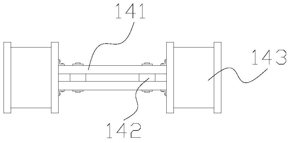
[0040] The activity limiting structure 143 includes a side plate 43a, a rolling structure 43b, and a fixing structure 43c. The rolling structure 43b is embedded and installed inside the side plate 43a, and the fixing structure 43c is arranged and welded between the side plates 43a.

[0041] refer to Figure 6 The rolling structures 43b are provided in multiples and every group of four is evenly distributed inside the side plates 43a, the fixed structure 43c separates the two side plates 43a, stabilizes the side plates 43a, and then moves better to adjust the height.

[0042] refer to Figure 9 , the fixed structure 43c includes a limiting plate c1, an adjusting rod c2, a spacer structure c3, and a slot c4. Between the plates c1, the clamping groove c4 is set on the inner side of the limiting plate c1 and is an integrated structur...


PUM


Abstract

The invention discloses a rotary wing hoist, the structure of which comprises a mounting and fixing structure, a support column, a rotating seat, a bracket, a motor, a hanger, and a suspension cable. The upper end of the support column, the bracket is installed horizontally on the right side of the rotating base, the motor is fixed on the upper end of the bracket through bolts, the hanger is installed obliquely on the left side of the rotating base, and the installation and fixing structure includes a connecting frame, a spacer, a fixing plate, and a mounting frame. The two sides of the support frame are equipped with activity limiting structures, which can be adjusted according to their actual height while being used with the utility pole, and two-way support is carried out to improve the stability of the erection and prevent the hoisting and lifting of the electric equipment from being affected Obstruction: A fixed structure is set between the side plates, which stabilizes the fixation and prevents offset, making it more stable during the hoisting and lifting of the power equipment, and preventing the tilt from affecting the hoisting and lifting of the power equipment.

Description

technical field [0001] The invention belongs to the field of hoists, and in particular relates to a rotary wing hoist. Background technique [0002] The rotary wing hoist is mainly used for hoisting and lifting objects, reducing the labor cost of people. In the substation site, there are many power equipment, and these power equipment are usually relatively large and heavy. When replacing these power equipment, due to the dense distribution of the power grid, the crane cannot play its role in hoisting here. Therefore, when replacing the power equipment in the substation site, it is necessary to use the rotor hoist, and it is better to use it in a small space. The equipment is hoisted and promoted, but the prior art has the following deficiencies: [0003] Since the electrical equipment is heavy and needs to be hoisted to a high place, when the height of the hoist is not enough, it is necessary to add a bracket at the bottom to meet the platform on which the electrical equip...

Claims


Application Information

Patent Timeline
Patent Type & Authority Patents(China)
IPC IPC(8): B66C23/84B66C23/78B66C23/62B66C13/08H02B3/00
CPCB66C23/84B66C23/78B66C23/62B66C13/08H02B3/00
Inventor 吴红林
Owner 吴红林
Why Eureka
Try Eureka