Anti-theft lock structure of luggage case
A suitcase and anti-theft lock technology, which is applied in building locks, building structures, buildings, etc., can solve the problems of low structural strength of thick locks, complex anti-theft lock structural functions, and strong structural strength, so as to improve user experience and control manufacturing cost, and the effect of reducing secondary operations
- Summary
- Abstract
- Description
- Claims
- Application Information
AI Technical Summary
Problems solved by technology
Method used
Image

Examples
Embodiment 1
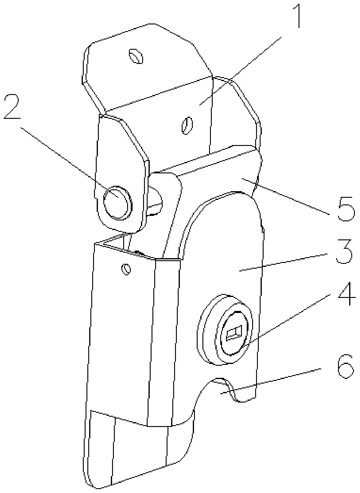
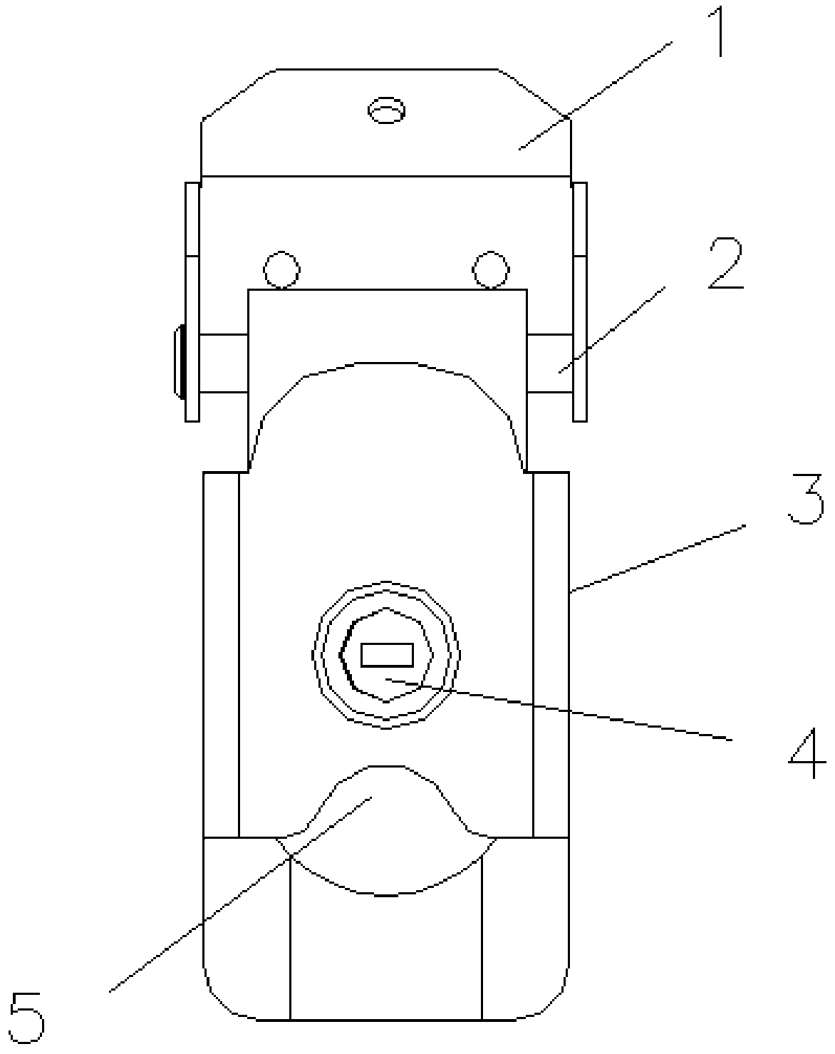
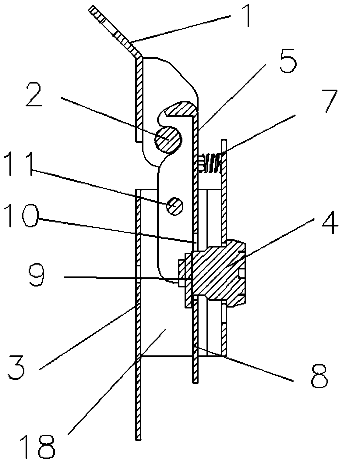
[0027] Such as Figure 1-4 As shown, the anti-theft lock structure of a suitcase of the present invention includes an upper lock body 1, a lower lock body 3, a dynamic lock catch 5, a fixed lock catch 2 and a lock cylinder.
[0028] The fixed lock catch 2 is cylindrical and arranged laterally on the upper lock body 1 .
[0029] On the lower lock body 3, there is a square tubular dynamic lock chamber 18. The dynamic lock catch 5 is arranged in the dynamic lock chamber 18 and is movably connected with the side wall of the dynamic lock chamber 18 through a pin shaft. The dynamic lock catch 5 includes a lock catch part. And the pressing part 8, the lock part is hook-shaped and protrudes from the upper part of the movable lock chamber 18 and locks with the fixed lock 2. The lower end of the press part 8 protrudes from the lower side of the driven lock 5, and the dynamic lock The left and right sides of the buckle 5 are bent, and the bent part is connected to the left and right sid...
Embodiment 2
[0033] On the basis of the structure of embodiment 1, in order to ensure that the upper and lower lock bodies 3 will not be disassembled from the outside of the suitcase, the installation point of the anti-theft lock is protected; the anti-theft lock structure of the suitcase is designed with an upper clamping mechanism and a lower clamping mechanism. mechanism.
[0034] The upper clamping mechanism includes a lock cover 12 and a lock cover clamping part 13. The lock cover 12 is covered outside the upper lock body 1 and connected with the upper end of the lower lock body 3. A threaded seat is arranged inside the lock cover 12, and the lock cover Clamping part 13 is arranged on the inboard of suitcase, and screw rod passes through lock cover clamping part 13, luggage case, upper lock body 1 successively and is connected with the screw seat of lock cover clamping part 13 to clamp upper lock body 1.
[0035] The lower clamping mechanism includes a first clamping part 14 and a sec...
PUM
 Abstract
Description
Claims
Application Information