A linear flexible variable stiffness adaptive artificial joint transmission device

A technology of artificial joints and transmission devices, which is applied to engine components, elastic couplings, sliding contact bearings, etc., can solve the problems of mismatching human knee joints, mismatching centers of rotation, complex geometric structures of human joints, etc. Adaptive features, effects that avoid rigid drive damage

Inactive Publication Date: 2021-01-29
王瑞
View PDF6 Cites 0 Cited by
  • Summary
  • Abstract
  • Description
  • Claims
  • Application Information

AI Technical Summary

Problems solved by technology

[0003] The robot body usually imitates the physiological structure of human lower limbs and joints. Robot joints are generally designed as single-axis drive joints, and the robot joints are bound to human joints. However, human joints have complex geometric structures and are not simple single-degree-of-freedom hinges. Mechanism; taking the knee joint as an example, its sagittal plane motion has a variable axis plane where rolling and sliding coexist, and the joint coupling surface has a non-constant rotation axis; if the human knee joint is driven by a traditional single-axis motor, it will cause both The mismatch of the rotation center will cause mismatching damage to the human knee joint. At the same time, the movement of the human joint is compliant, and the stiffness of different human joints is different. Directly binding the rigid robot joints to the human joints is easy to cause damage to the human joints. Deal Rigid Drive Damage

Method used


Image

  • A linear flexible variable stiffness adaptive artificial joint transmission device
  • A linear flexible variable stiffness adaptive artificial joint transmission device
  • A linear flexible variable stiffness adaptive artificial joint transmission device

Examples


Embodiment Construction

[0020] The present invention will be described in further detail below with reference to the accompanying drawings and specific embodiments, but the scope of implementation of the present invention is not limited thereto.

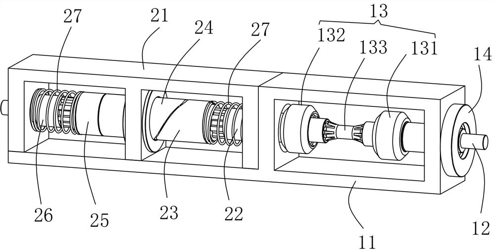
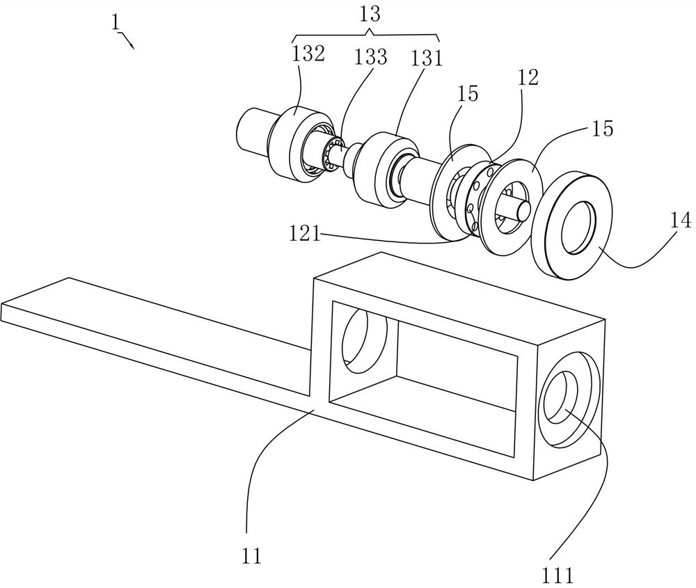
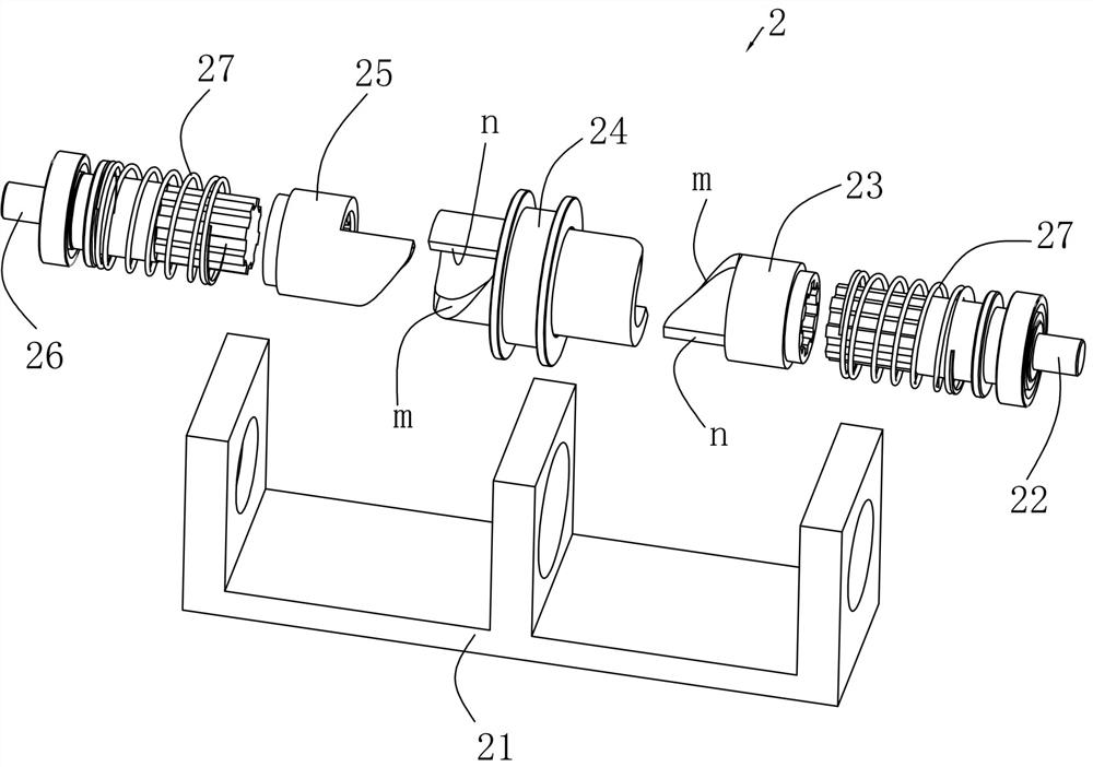
[0021] like Figure 1 to Figure 3 As shown, a linear flexible variable stiffness adaptive artificial joint transmission device described in this embodiment includes an input part 1 and an output part 2;

[0022] The input component 1 includes a drive shaft bracket 11, a disc-shaped input shaft 12 and a ball cage universal joint 13. One end of the drive shaft support 11 is provided with a slot 111 for installing the input shaft 12. The input shaft 12 is installed in the slot 111 through a shaft end cover 14 and two plane lubricating bearings 15, and it can move in the radial direction relative to the plane lubricating bearings 15. One end of the ball cage universal joint 13 passes through the first coupling It is drivingly connected with one end of the inpu...


PUM


Abstract

The invention discloses a linear flexible variable stiffness self-adaptive artificial joint transmission device, which includes an input part, which includes a drive shaft support, an input shaft and a ball cage universal joint. Shaft support, and it can move in the radial direction; also includes the output part, which includes the driven shaft support, two output shafts, two sliding buffer sleeves, inclined cams, one output shaft is connected with the universal joint of the ball cage, two The sliding buffer sleeves are slidingly connected to the two output shafts corresponding to the splines. Both ends of the inclined cam and the two sliding buffer sleeves are equipped with a thrust slope and a rigid transmission surface. The two ends of the inclined cam are respectively meshed with the two sliding buffer sleeves. , the phase angle between the thrust slopes at both ends of the slope cam is 180 degrees, and the direction is opposite, and the two output shafts are covered with torque buffer springs; the invention can realize the matching of the rotation centers of human joints and robot joints, and the flexible transmission of torque , to avoid damage to human joints.

Description

technical field [0001] The invention relates to a linear flexible variable stiffness self-adaptive artificial joint transmission device. Background technique [0002] With the increasing demand for exercise rehabilitation of disabled patients and joint sprain patients, robotic devices such as rehabilitation robots, exoskeleton robots, joint trainers, and gait correctors have been continuously developed, and certain rehabilitation training effects have been achieved. [0003] The robot body usually imitates the physiological structure of the lower limbs and joints of the human body. The robot joints are generally designed as single-axis drive joints, and the robot joints are bound to the human joints. However, the human joints have complex geometric structures and are not simple single-degree-of-freedom hinges. mechanism; take the knee joint as an example, the sagittal motion has a variable axis plane with rolling and sliding coexistence, and the joint coupling surface has a ...

Claims


Application Information

Patent Timeline
Patent Type & Authority Patents(China)
IPC IPC(8): F16D3/223F16D3/04F16D7/00F16C17/08F16N1/00A61H1/02A61F5/01
CPCA61F5/0123A61H1/0237A61H1/024A61H2201/1659A61H2205/10A61H2205/102F16C17/08F16D3/04F16D3/223F16D7/00F16N1/00
Inventor 王瑞李雷热合木江·木合塔尔王建
Owner 王瑞
Why Eureka
Try Eureka