Display unit, near-eye display optical module and near-eye display system
A display unit and light technology, applied in optics, optical components, instruments, etc., can solve the problems of unclear display images and low display brightness, and achieve the effect of improving image quality and high display clarity
- Summary
- Abstract
- Description
- Claims
- Application Information
AI Technical Summary
Problems solved by technology
Method used
Image

Examples
Embodiment 1
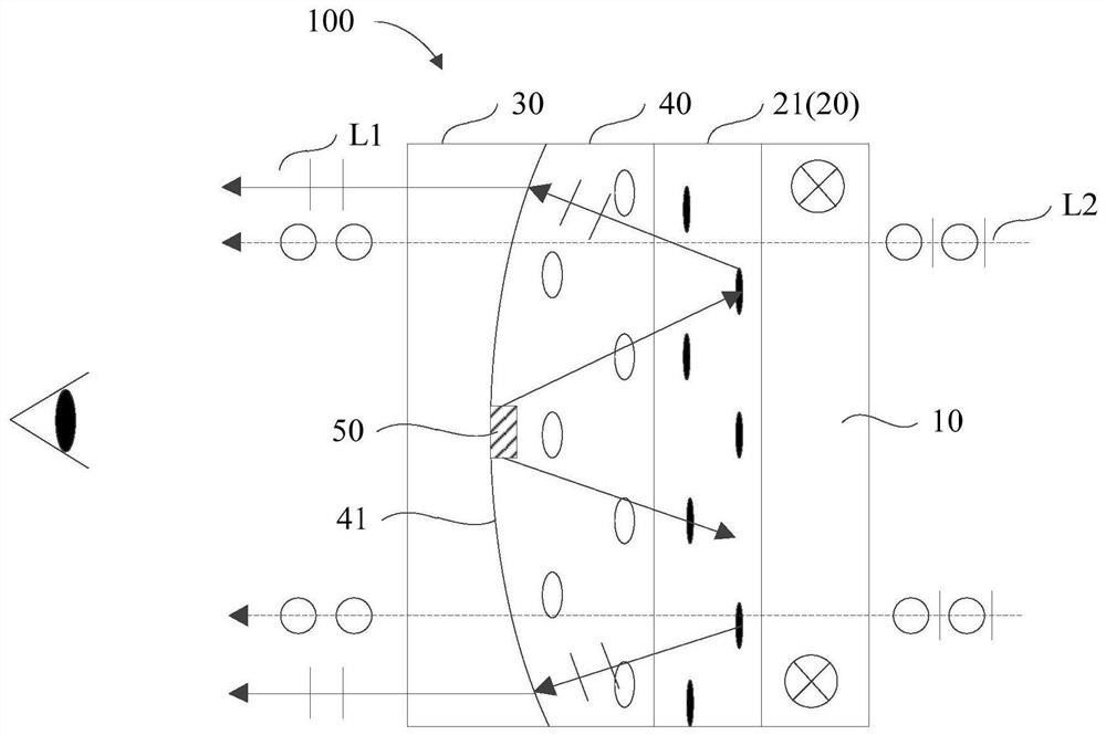
[0055] figure 1 A schematic structural diagram of a display unit provided with a quantum rod layer provided in Embodiment 1 of the present invention. figure 2 A schematic structural diagram of a display unit provided with a wire grid polarizing layer provided in Embodiment 1 of the present invention.
[0056] The inventors of the present invention found in the actual research process that in the current near-eye display system, in order to ensure the clarity of the image in the human eye, it is usually necessary to adjust the optical path of the light that the image enters into the human eye. However, since the image of the near-eye display system includes the near-eye display image of the virtual screen and the external transmission image including the real screen, the current optical path adjustment process of the light will simultaneously generate the imaging optical path of the near-eye display image and the imaging optical path of the external transmission image. Howeve...
Embodiment 2
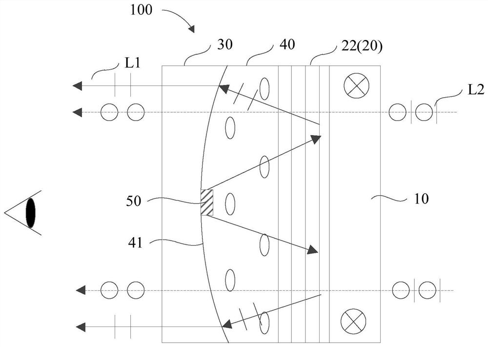
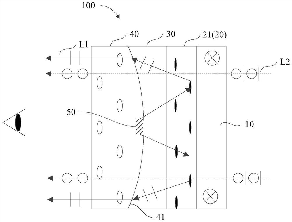
[0094] image 3 A schematic structural diagram of a display unit provided with a quantum rod layer provided in Embodiment 2 of the present invention. refer to image 3 As shown, on the basis of the first embodiment above, the second embodiment of the present invention also provides a display unit 100 with another structure. Compared with the first embodiment, the difference between the second embodiment and the first embodiment is that the refractive index matching layer 30 and the placement positions of the anisotropic material layer 40 are different.
[0095] Specifically, the refractive index matching layer 30 is stacked between the anisotropic material layer 40 and the optical characteristic changing layer 20 .
[0096] It should be noted that, referring to image 3 As shown, the refractive index matching layer 30 is attached to the surface of the optical characteristic changing layer 20 away from the linear polarization layer 10 , and the distance from the light emitti...
Embodiment 3
[0100] Figure 4 A schematic structural diagram of a near-eye display optical module provided by Embodiment 3 of the present invention. refer to Figure 4 As shown, on the basis of the above-mentioned first and second embodiments, the third embodiment of the present invention further provides a near-eye display optical module 200 , and the near-eye display optical module 200 includes the above-mentioned display unit 100 .
[0101] Specifically, in the near-eye display optical module 200, the multiple display units 100 include at least one first display unit 201 provided with a wire grid polarizing layer 22, at least one second display unit 202 provided with a red quantum rod layer 21 And at least one third display unit 203 provided with the green quantum rod layer 21 .
[0102] The first display unit 201, the second display unit 202 and the third display unit 203 are tiled in an array arrangement, wherein the light emitted by the light emitting elements of the first display ...
PUM
 Abstract
Description
Claims
Application Information
 - R&D
- Intellectual Property
- Life Sciences
- Materials
- Tech Scout
- Unparalleled Data Quality
- Higher Quality Content
- 60% Fewer Hallucinations
Browse by: Latest US Patents, China's latest patents, Technical Efficacy Thesaurus, Application Domain, Technology Topic, Popular Technical Reports.
© 2025 PatSnap. All rights reserved.Legal|Privacy policy|Modern Slavery Act Transparency Statement|Sitemap|About US| Contact US: help@patsnap.com