A method for restraining the deformation of existing cutting gravity retaining wall

A gravity-type retaining wall technology, applied in construction, artificial island, geometric CAD, etc., can solve the problems of low economy, regardless of the bearing capacity of existing road cutting gravity-type retaining walls, to improve economy and avoid demolition and reconstruction. , the effect of reducing the load

Active Publication Date: 2022-08-05
CHINA RAILWAY ERYUAN ENG GRP CO LTD
View PDF10 Cites 0 Cited by
  • Summary
  • Abstract
  • Description
  • Claims
  • Application Information

AI Technical Summary

Problems solved by technology

[0006] The purpose of the present invention is to overcome the problem existing in the prior art that the carrying capacity of the existing gravity retaining wall of the cutting is not considered when reinforcing the existing gravity retaining wall of the cutting, which leads to low economic efficiency. The existing cutting gravity retaining wall deformation method improves economy and saves engineering investment under the premise of ensuring safety

Method used


Image

  • A method for restraining the deformation of existing cutting gravity retaining wall
  • A method for restraining the deformation of existing cutting gravity retaining wall
  • A method for restraining the deformation of existing cutting gravity retaining wall

Examples


Embodiment 1

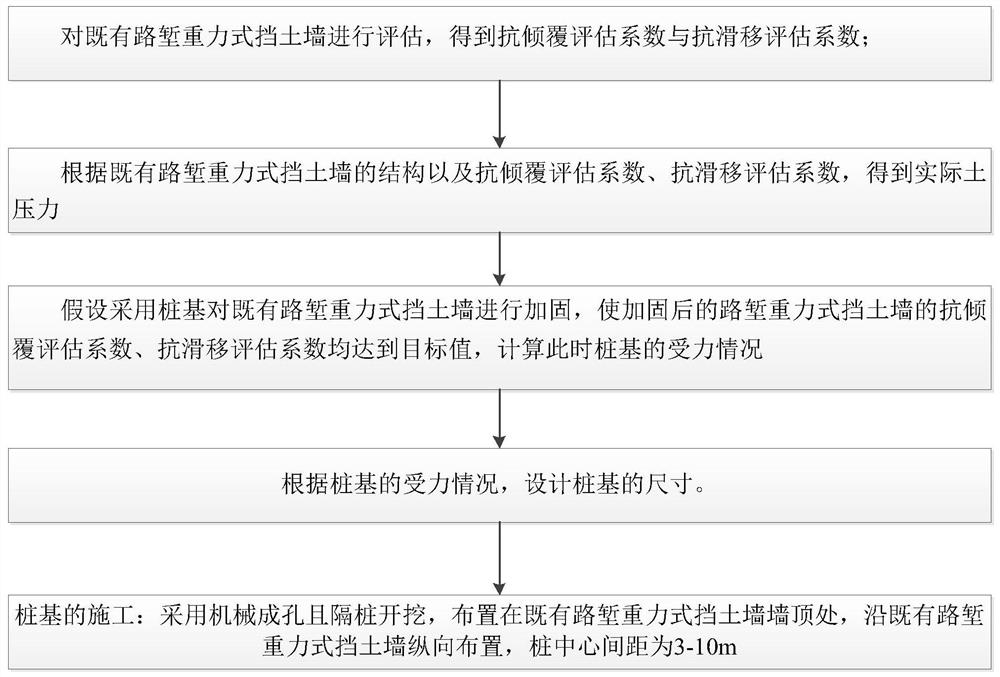
[0058] like figure 1 , a method for suppressing the deformation of an existing cutting gravity retaining wall 1, comprising:

[0059] S100 evaluates the existing cutting gravity retaining wall 1, and obtains the actual anti-overturning evaluation coefficient and the actual anti-slip evaluation coefficient;

[0060] S200 obtains the actual earth pressure according to the structural force of the existing cutting gravity retaining wall 1 and the actual anti-overturning evaluation coefficient and the actual anti-slip evaluation coefficient;

[0061] S300 assumes that pile foundations are used to reinforce the existing cutting gravity retaining wall 1, so that the target anti-overturning evaluation coefficient and target anti-sliding evaluation coefficient of the reinforced road cutting gravity retaining wall are used to calculate the stress condition of the pile foundation;

[0062] S400 designs the size of the pile foundation according to the stress condition of the pile foundat...

Embodiment 2

[0140] Step 1 Evaluation of existing cutting gravity retaining walls1

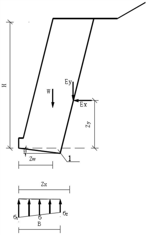
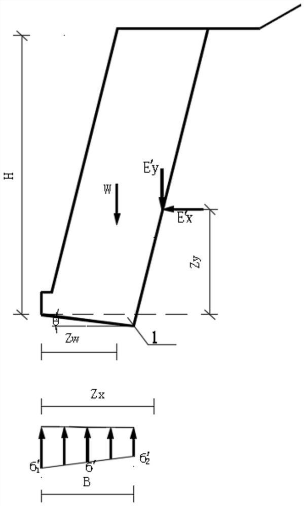
[0141] like Figure 7 , it is known that a single-line Class I railway has a cutting gravity retaining wall 1, the retaining wall is 6.0m high and 1.4m deep. The slope of the back slope is 1:-0.25, the width of the wall toe step is 0.25m, and the height of the wall toe step is 0.6m. is 0.3, see details for details Image 6 . The original design anti-overturning stability safety factor is 2.1847, and the original design anti-slip stability safety factor is 1.316.

[0142] According to the safety evaluation methods and means, the anti-overturning and anti-slip stability of the existing cutting gravity retaining wall 1 are evaluated, and the anti-overturning and anti-slip evaluation coefficients K are obtained respectively. 02 = 1.5 and K C2 = 1.1.

[0143] The second step is to calculate the actual earth pressure of the existing cutting gravity retaining wall 1

[0144] According to the original desig...


PUM


Abstract

The invention discloses a method for restraining the deformation of an existing road cutting gravity type retaining wall, which fully considers the partial bearing capacity of the existing road cutting gravity type retaining wall. A row of bored piles is arranged behind the wall to reduce the existing The earth pressure of the cutting gravity retaining wall improves the anti-slip and anti-overturning safety of the structure, and the size of the pile foundation is designed according to the force of the existing cutting gravity retaining wall and the new pile foundation. Compared with the existing technology The invention provides a new calculation and design method considering the bearing effect of the existing cutting gravity retaining wall, which avoids the demolition and reconstruction of the existing retaining wall, reduces the load shared by the pile foundation, and optimizes the size of the pile foundation. , thereby reducing the project investment and improving the economy under the premise of ensuring safety.

Description

technical field [0001] The invention relates to the technical field of geotechnical engineering, in particular to a method for restraining the deformation of existing road cutting gravity retaining walls. Background technique [0002] In the construction of infrastructure such as railways and highways, gravity retaining walls are widely used in cutting sections due to their large numbers. The nature of the rock and soil behind the cutting gravity retaining wall is complex. In the actual use process, due to natural factors such as earthquakes, rain erosion, changes in geological conditions and human factors in early construction, the gravity retaining wall has a certain sliding deformation or deformation. The disease of camber deformation will reduce the stability of the gravity retaining wall against sliding or overturning, and the risk of sliding and overturning damage may occur in long-term use. [0003] Although the gravity retaining wall has a certain sliding deformatio...

Claims


Application Information

Patent Timeline
Patent Type & Authority Patents(China)
IPC IPC(8): G06F30/13G06F30/20E02D29/02E02D27/12G06F119/14
CPCE02D29/02E02D27/12
Inventor 魏永幸吴邵海刘菀茹王智猛周波付正道褚宇光
Owner CHINA RAILWAY ERYUAN ENG GRP CO LTD
Why Eureka
Try Eureka