Composite foundation reinforced cantilever retaining wall structure and construction method thereof

A composite foundation and cantilever-type technology, which is applied in the direction of foundation structure engineering, underwater structures, artificial islands, etc., can solve the problems of high bearing capacity of the foundation, increase in the amount of steel and concrete, instability and damage, etc., to improve the resistance Deformation ability, increase in applicable wall height, effect of ensuring connection strength

Pending Publication Date: 2017-12-26
CHANGJIANG SURVEY PLANNING DESIGN & RES
View PDF7 Cites 3 Cited by
  • Summary
  • Abstract
  • Description
  • Claims
  • Application Information

AI Technical Summary

Problems solved by technology

When the above-mentioned engineering construction is located in coastal areas, river and lake banks, soft soil areas, and deep overburden areas, the stratum structure is mostly composed of silty sand, silt, silty clay, and silty soil. The traditional cantilever retaining wall structure cannot To meet the stability requirements of itself and the filling body behind the wall, it must be combined with the retaining wall in other ways to jointly bear the filling pressure behind the wall
[0003] When encountering the above-mentioned poor geological conditions, due to the low bearing capacity of the foundation, the retaining wall and the filling body behind the wall will experience large deformation and even failure. layer foundation use
Chinese patents CN103321243B, CN103410167B, and CN104389320B respectively use steel pipe micropiles, cast-in-situ piles, and pipe piles to reinforce the foundation of the retaining wall, but the above-mentioned piles are all plain concrete or reinforced concrete structures, and the construction process is complicated, and the construction period is long. high
[0004] The applicable height of the cantilever retaining wall is generally less than 6 meters. When the wall height continues to increase, only relying on the retaining wall itself to resist the filling pressure will cause a sharp increase in the amount of steel and concrete. Walls are less economical

Method used


Image

  • Composite foundation reinforced cantilever retaining wall structure and construction method thereof
  • Composite foundation reinforced cantilever retaining wall structure and construction method thereof

Examples


Embodiment Construction

[0022] The implementation of the present invention will be described in detail below in conjunction with the accompanying drawings, but they do not constitute a limitation of the present invention, and are merely examples; at the same time, the advantages of the present invention will become clearer and easier to understand through the description.

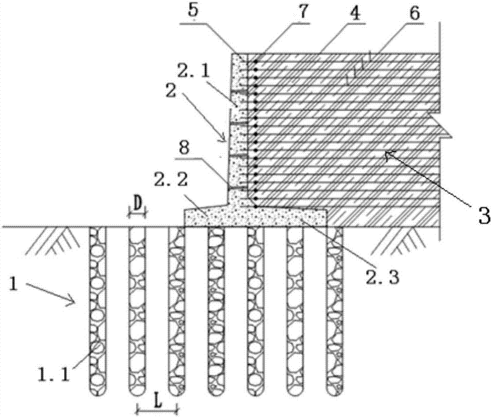
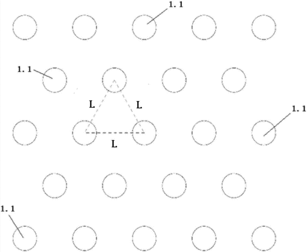
[0023] The composite foundation 1 is a composite foundation 1 formed by vibro-penetrating gravel piles 1.1 after the original soft soil foundation or deep overburden foundation is treated by the vibro-impact replacement method, and its bearing capacity should meet the anti-sliding and anti-sliding resistance of the retaining wall. Overturning requirements. The composite foundation 1 bearing capacity R sp =[1+m(n-1)]×R s , R s Is the bearing capacity of the original foundation; m is the replacement rate of gravel piles, m=A P / A s , A P Is the cross-sectional area of ​​the gravel pile, A s Is the area of ​​the composite foundation; n ...


PUM


Abstract

The invention discloses a composite foundation reinforced cantilever retaining wall structure and a construction method of the composite foundation reinforced cantilever retaining wall structure. The composite foundation reinforced cantilever retaining wall structure comprises a composite foundation (1), a cantilever retaining wall (2), a geogrid (3) and a filling body (4). The composite foundation (1) is located underground and composed of multiple vibro-replacement crushed stone piles (1.1). The cantilever retaining wall (2) is located above the composite foundation (1). The inner side of the cantilever retaining wall (2) is provided with the filling body (4). The geogrid (3) is transversely arranged on the lower portion of the filling body (4). The composite foundation reinforced cantilever retaining wall structure overcomes the defects that in the prior art, a traditional cantilever retaining wall structure cannot meet the stability requirements of the cantilever retaining wall structure and the filling body behind the wall and has the advantages that the construction technology is simple, convenient and rapid.

Description

Technical field [0001] The invention relates to the technical fields of water conservancy, highways and civil engineering, and more specifically to a composite foundation reinforced cantilever retaining wall structure and a construction method. Background technique [0002] In the filling process of the revetment body, highway subgrade, spoil yard and other projects, cantilever retaining walls are usually used to resist the pressure of the filling. When the above construction is located in coastal areas, rivers and lakes beaches, soft soil areas, and deep overburden areas, the stratum structure is mostly composed of silt, silt, silty clay, and silty soil. The traditional cantilever retaining wall structure cannot To meet the stability requirements of itself and the filling body behind the wall, other methods must be used in combination with the retaining wall to jointly bear the filling pressure behind the wall. [0003] When encountering the above-mentioned poor geological condit...

Claims


Application Information

Patent Timeline
Patent Type & Authority Applications(China)
IPC IPC(8): E02D29/02E02D27/16
CPCE02D27/16E02D29/02E02D29/0241E02D2300/0084
Inventor 刘波牛运华石志超陈培
Owner CHANGJIANG SURVEY PLANNING DESIGN & RES
Why Eureka
Try Eureka