Shielding current eliminating device for high-temperature superconducting coil

A shielding current and high-temperature superconducting technology, which is applied to superconducting magnets/coils, circuits, electrical components, etc., can solve problems such as slow changes in shielding current, affecting the distribution of high-temperature superconducting magnets, and magnetic field drift

Active Publication Date: 2020-06-09
INST OF ELECTRICAL ENG CHINESE ACAD OF SCI
View PDF4 Cites 1 Cited by
  • Summary
  • Abstract
  • Description
  • Claims
  • Application Information

AI Technical Summary

Problems solved by technology

The generation of shielding current leads to uneven distribution of conduction current inside the high-temperature superconducting strip, which seriously affects the distribution of the magnetic field in the homogeneous region of the high-temperature superconducting magnet, and deteriorates the uniformity of

Method used


Image

  • Shielding current eliminating device for high-temperature superconducting coil
  • Shielding current eliminating device for high-temperature superconducting coil
  • Shielding current eliminating device for high-temperature superconducting coil

Examples


Embodiment Construction

[0016] The present invention will be further described below in conjunction with the accompanying drawings and specific embodiments.

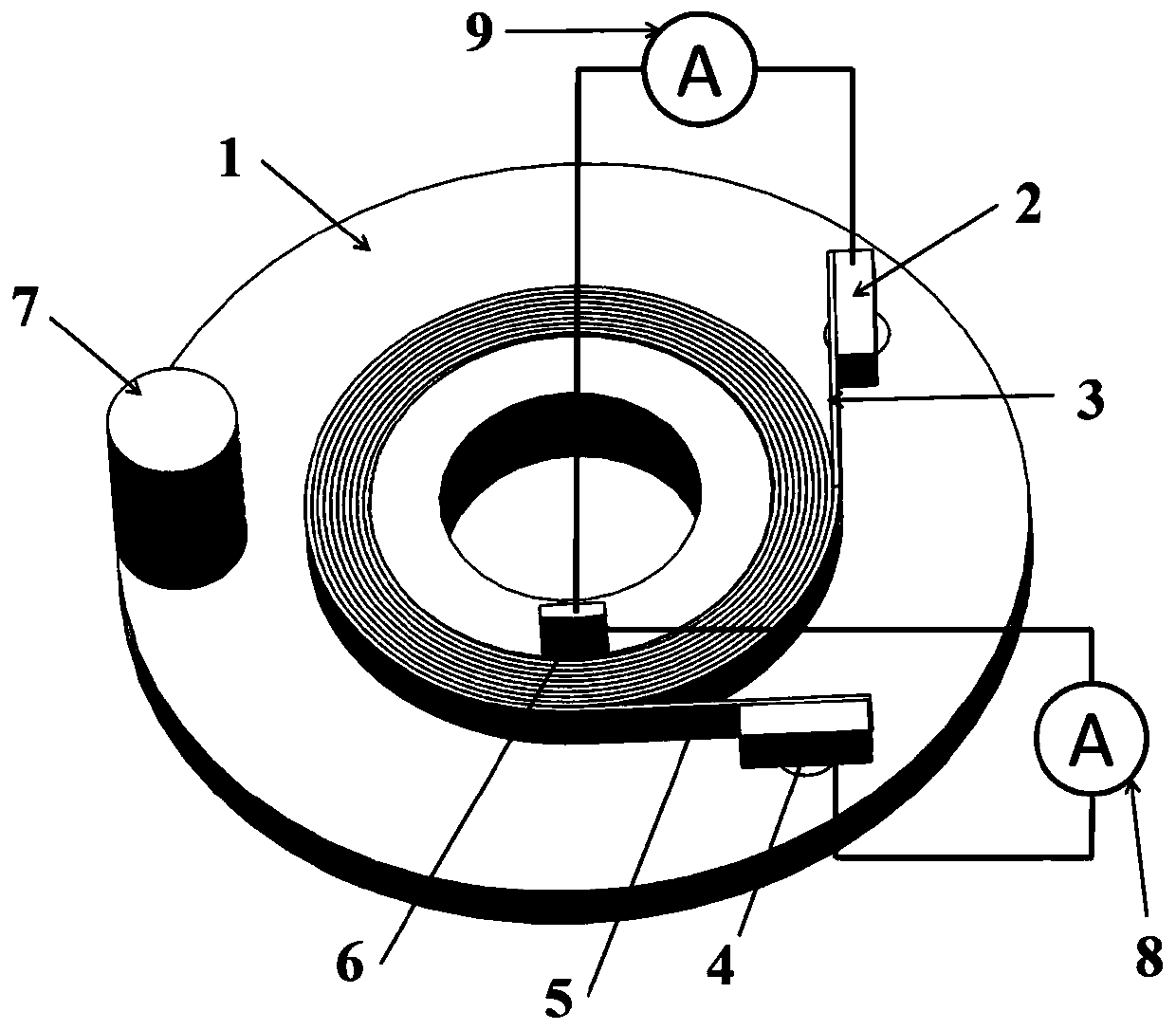
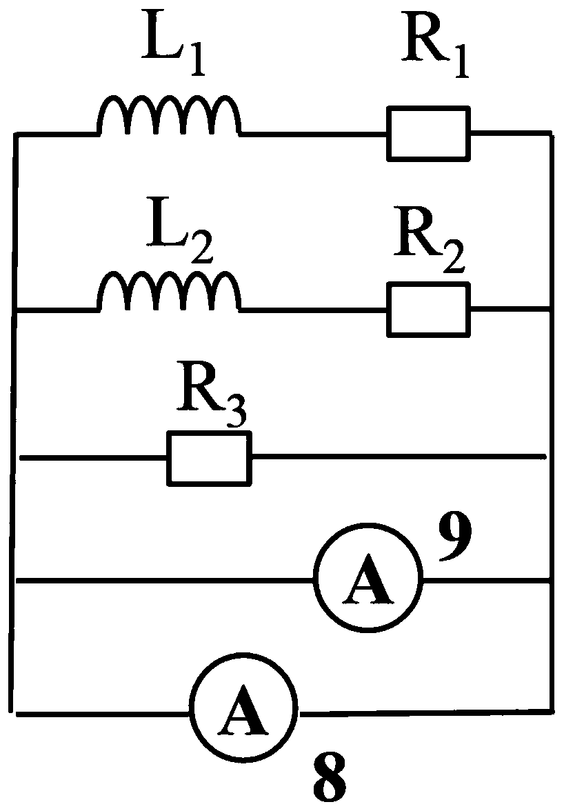
[0017] like Figure 1-Figure 5 As shown, the embodiment of the present invention consists of a skeleton 1, a high temperature superconducting strip 3, a stainless steel strip 5, a first terminal 2, a second terminal 4, a third terminal 6, a cold head 7, an AC power supply 8 and a DC The power supply 9 is composed.

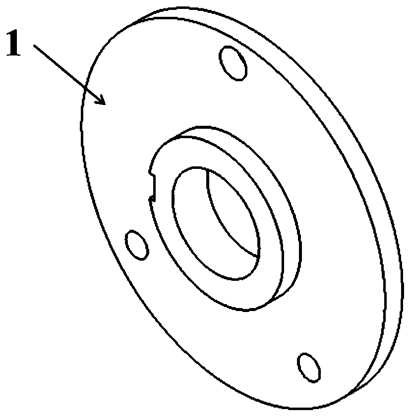
[0018] The skeleton 1 is located at the bottom of the whole device, the surface of the high-temperature superconducting strip 3 and the stainless steel strip 5 are not wrapped with insulating materials, but are wound side by side on the skeleton 5, the stainless steel strip is located on the outside, and the high-temperature superconducting strip is located on the inside. The inner side of the frame 1 is provided with a groove for installing the third terminal post 7 . There are round holes on the outer side of the skeleton 1, an...


PUM


Abstract

The invention relates to a shielding current eliminating device for a high-temperature superconducting coil. The device is composed of a framework, a cold head, a high-temperature superconducting strip, a stainless steel strip, binding posts, an alternating-current power source and a direct-current power source. The surfaces of the high-temperature superconducting strip and the stainless steel strip are not wrapped with an insulating material and are wound on the framework side by side; A groove is formed in the inner side of the framework; the groove at the inner side of the framework is provided with one binding post; round holes are formed in the outer side of the framework; the other binding post and the cold head are respectively mounted in the outer side of the framework. The inner sides of the high-temperature superconducting strip and the stainless steel strip share the binding post; the outer sides of the high-temperature superconducting strip and the stainless steel strip arerespectively connected with the independent binding posts; the high-temperature superconducting strip is connected with the direct-current power source to generate a static magnetic field in the center area of the coil; the stainless steel strip is connected with the alternating-current power source to provide current flowing between the layers of the high-temperature superconducting strip and the stainless steel strip to cause interlayer resistance heating, so that critical current in the high-temperature superconducting coil is reduced, and the influence of shielding current is eliminated.

Description

technical field [0001] The invention relates to a shielding current eliminating device, in particular to a high temperature superconducting coil shielding current eliminating device. Background technique [0002] In recent years, superconducting magnets have been widely used in many fields such as national economy and scientific research. Compared with traditional low-temperature superconducting wires, high-temperature superconducting tapes, such as commercial Bi-2223 and REBCO tapes, have higher critical temperature, critical magnetic field and mechanical strength, and have been highly valued by researchers since their birth. The working characteristics are continuously improved. Due to its excellent current-carrying performance and higher operating temperature range, high-temperature superconducting magnets play an irreplaceable role in many fields, such as space strong magnetic field applications, extremely high-field superconducting magnetic resonance spectrometers, con...

Claims


Application Information

Patent Timeline
IPC IPC(8): H01F6/00H01F6/06
CPCH01F6/00H01F6/06H01F6/065H01F2006/001
Inventor 王磊王秋良刘建华秦朗王康帅
Owner INST OF ELECTRICAL ENG CHINESE ACAD OF SCI
Why Eureka
Try Eureka