
Three-level BUCK circuit control method and charger circuit control method and system

A technology of circuit control and control system, which is applied in the direction of control/regulation system, battery circuit device, circuit device, etc. It can solve the problem of low-frequency fluctuation of output voltage, fluctuation of FC voltage of DC blocking capacitor, and inability to effectively ensure balanced control of output voltage of equalizing capacitor And other issues

Active Publication Date: 2020-06-09
CRRC QINGDAO SIFANG ROLLING STOCK RES INST
View PDF1 Cites 3 Cited by
  • Summary
  • Abstract
  • Description
  • Claims
  • Application Information

AI Technical Summary

Problems solved by technology

In this three-loop control method, due to the different switching characteristics of the switching tubes Q1 and Q2, the voltage equalizing loop adopts open-loop control, and the difference between the voltages of the two output capacitors is used as the feedback value, which cannot effectively guarantee the output voltage of the equalizing capacitors C1 and C2. balance control
At the same time, the open-loop control method is commonly used in the post-stage resonant conversion circuit, but due to the voltage fluctuation of the DC blocking capacitor FC brought about by the voltage equalization control of the output capacitors C1 and C2 of the three-level BUCK circuit, coupling to the output terminal of the resonant circuit may easily cause the output voltage to exist. Low frequency pulsation

Method used


Image

  • Three-level BUCK circuit control method and charger circuit control method and system
  • Three-level BUCK circuit control method and charger circuit control method and system
  • Three-level BUCK circuit control method and charger circuit control method and system

Examples


Embodiment Construction

[0054] Specific embodiments of the present invention will be further described below in conjunction with the accompanying drawings.

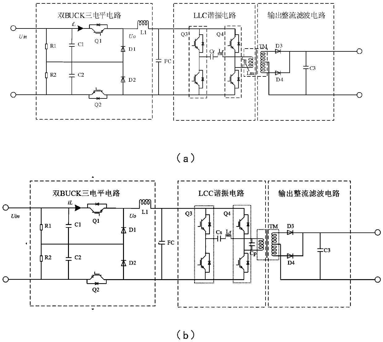
[0055] Such as figure 1 As shown, the charger circuit can adopt the form of BUCK circuit + LLC or LCC resonant circuit to realize the functions of adjustable DC voltage output, low noise and light weight of the charger.

[0056] Such as figure 1 As shown in (a), when the charger circuit adopts a three-level dual BUCK circuit + LLC resonant circuit topology, it includes a three-level BUCK circuit, an LLC resonant conversion circuit, and an output rectification filter circuit. For a three-level BUCK circuit, both The piezoresistors R1, R2 and voltage equalizing capacitors C1, C2 form a half-bridge voltage equalizing circuit. The midpoint of the voltage equalizing resistors R1, R2 connected in series is connected to the midpoint of the voltage equalizing capacitors C1, C2 connected in series to realize input voltage equalization; the switching tub...


PUM


Abstract

The invention relates to a three-level BUCK circuit control method and a charger circuit control method and system. The three-level BUCK circuit control method comprises the steps of carrying out PIDclosed-loop voltage control on two voltage-sharing capacitors of a three-level BUCK circuit, enabling the output voltage of each voltage-sharing capacitor to be Uin / 2, and correcting the PWM duty ratios of two switching tubes; and meanwhile, taking the feed-forward voltage compensation value of the three-level BUCK circuit as a given voltage target value of a resonant conversion circuit, carryingout PID closed-loop voltage control on the resonant conversion circuit, and correcting the PWM duty ratio of a switching tube of the resonant conversion circuit. According to the invention, voltage-sharing closed-loop control is added to guarantee voltage sharing of the voltage-sharing capacitors at the front end of the three-level BUCK circuit. Meanwhile, the voltage closed-loop compensation of the resonant conversion circuit is added, so that the effectiveness of the resonant circuit is ensured, the influence of the low-frequency pulsation of the three-level BUCK circuit on the output voltage is eliminated, the output voltage is stable, and the coupling control of the BUCK circuit and the post-stage resonant circuit is improved.

Description

technical field [0001] The invention belongs to the technical field of charger circuit control, and in particular relates to a three-level BUCK circuit control method, a charger circuit control method and a system. Background technique [0002] The existing charger circuit mainly includes a three-level BUCK circuit, a resonant conversion circuit, and an output rectification filter circuit. The three-level BUCK circuit performs voltage equalization and voltage stabilization control. circuit for rectification and filtering, such as figure 1 Shown is the topological structure of the main circuit of the charger circuit. [0003] The existing three-level BUCK circuit mainly collects the three-loop control method of the voltage outer loop, the current inner loop, and the voltage equalizing loop. The voltage equalizing loop adopts open-loop control, and the voltage U1 on the output capacitor C1 and the voltage U2 on the output capacitor C2 are collected for differential transmissi...

Claims


Application Information

Patent Timeline
Patent Type & Authority Applications(China)
IPC IPC(8): H02M3/156H02M3/335H02J7/00
CPCH02M3/156H02M3/33507Y02B70/10
Inventor 王博刘天宇吴强周双雷王旭阳
Owner CRRC QINGDAO SIFANG ROLLING STOCK RES INST
Learn More