

Automatic pruning control device for green belt
An automatic pruning and control device technology, which is applied to hedge pruning equipment, cutting tools, cutting equipment, etc., can solve the problems of labor load, inconvenient pruning knife adjustment, pruning efficiency discount, etc., to delay the evaporation of water and save work Amount of labor, easy to adjust the effect of use
- Summary
- Abstract
- Description
- Claims
- Application Information
AI Technical Summary
Problems solved by technology
Method used
Image

Examples
Embodiment 1
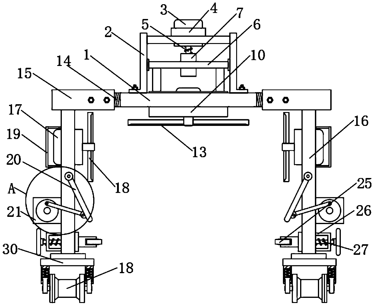
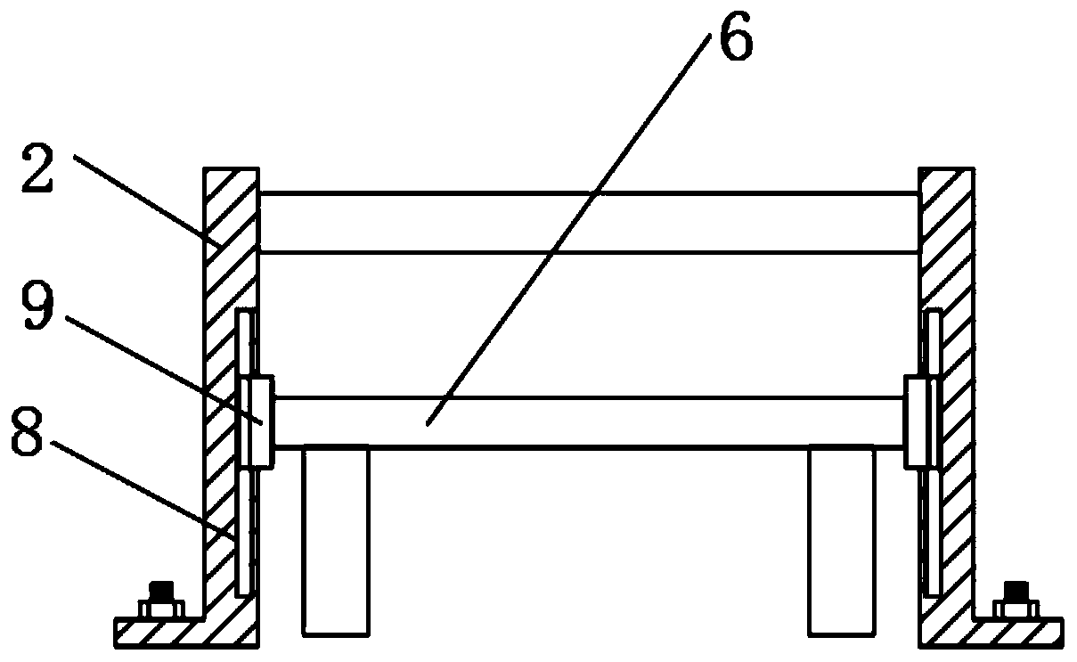
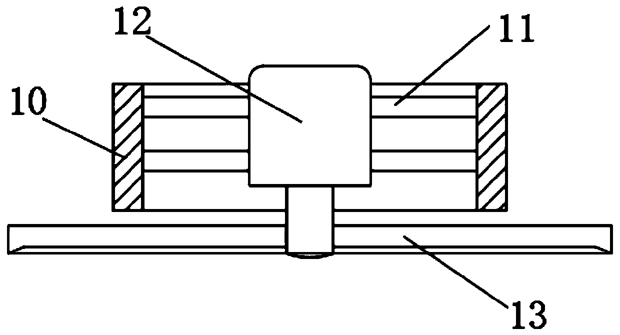
[0029] see Figure 1-6 , the green belt automatic pruning control device, including a fixed plate 1, is characterized in that: the top of the fixed plate 1 is fixedly connected with a mounting frame 2, the middle part of the mounting frame 2 is fixedly installed with a first motor 3, and the output end of the first motor 3 is fixedly connected with a second motor. A screw 5, the inner side of the mounting frame 2 is slidably connected with a sliding frame 6, the middle part of the sliding frame 6 is fixedly connected with a fitting cylinder 7, the first screw 5 is matched and installed in the fitting barrel 7, and the bottom end of the sliding frame 6 is fixedly connected with a lifting cylinder 10, The inner wall of the lifting cylinder 10 is fixedly connected with a support rod 11, the other end of the support rod 11 is fixedly connected with a second motor 12, the output end of the second motor 12 is fixedly connected with a first trimmer 13, and the two ends of the fixed pl...
Embodiment 2
[0032] see Figure 1-6 , made further improvements on the basis of Embodiment 1: the middle part of the top of the mounting frame 2 is fixedly connected with a stabilizing cylinder 4, and the first motor 3 is fixedly installed inside the stabilizing cylinder 4; the inside of the mounting frame 2 is provided with a first sliding groove 8, and A slide groove 8 is slidably connected with a sliding block 9, and the sliding block 9 is fixedly connected to both sides of the sliding frame 6; a third motor 17 is fixedly installed on both sides of the mounting plate 16, and the output end of the third motor 17 is fixedly connected to a second motor. The trimming knife 18 ; the outer side of the mounting plate 16 is fixedly connected with a protective cover 19 , and the protective cover 19 is located on the outer side of the third motor 17 .
[0033] In this embodiment, the stability of the installation of the first motor 3 can be ensured by the stabilizing cylinder 4, and the sliding b...
Embodiment 3
[0035] see Figure 1-6 On the basis of Embodiment 1, a further improvement has been made: the middle part of the mounting plate 16 is rotatably connected with a rotating plate 20, the outer wall of the mounting plate 16 is fixedly installed with a fourth motor 21, and the output end of the fourth motor 21 is fixedly connected with a rotating disc 22, and the rotation One end of the disc 22 is rotatably connected with a transmission rod 23 , and the other end of the transmission rod 23 is rotatably mounted on one end of the rotating plate 20 .
[0036] In this embodiment, in the process of trimming the green belt, the fourth motor 21 is used to drive the rotating disk 22 to rotate, and then the rotating disk 22 drives the rotating plate 20 to swing in a certain arc through the rotating rod 23, so that the trimmed The residual branches are transported to the bottom of the green belt.
PUM
 Abstract
Description
Claims
Application Information