Thrombus taking device

A component and slender technology, applied in the field of thrombectomy devices, can solve the problems of thrombus falling off, grids of thrombectomy stents not being in the optimal size and separation, etc., to achieve the effect of effective capture

Active Publication Date: 2020-06-12
LIFETECH SCI (SHENZHEN) CO LTD
View PDF7 Cites 6 Cited by
  • Summary
  • Abstract
  • Description
  • Claims
  • Application Information

AI Technical Summary

Problems solved by technology

[0005] 1. The grid of the thrombectomy stent is the passage for the thrombus to enter its interior, so the size of the grid determines the effect of the thrombus retrieval stent on capturing the thrombus. Usually, the integral thrombectomy stent has the largest grid size when it is fully expanded. The thrombus retrieval stent is always in a compressed state in the blood vessel, which makes the grid of the thrombus retrieval scaffold not in an optimal size, especially when catching white blood clots / hard thrombi rich in white blood cells (the thrombus is rich in fibers and has strong viscoelasticity). , studies have shown that the force required to compress leukocyte-rich white thrombus / hard thrombus is 9mN / mm 2 ), the radial force of the self-expanding stent is not enough to allow the mesh rods of the stent to penetrate into the white thrombus, and the mesh size of the thrombectomy stent cannot allow the white thrombus to enter the thrombus retrieval stent from the mesh
[0006] 2. The local deformation of the thrombectomy stent will cause the grid associated with this part to deform simultaneously, which will cause the overall diameter of the thrombectomy stent to become smaller when the thrombectomy stent passes through the curved vessel part during the retraction process, thereby separating from the blood vessel , causing the thrombus to dislodge from the stent

Method used


Image

  • Thrombus taking device
  • Thrombus taking device
  • Thrombus taking device

Examples


Embodiment 1

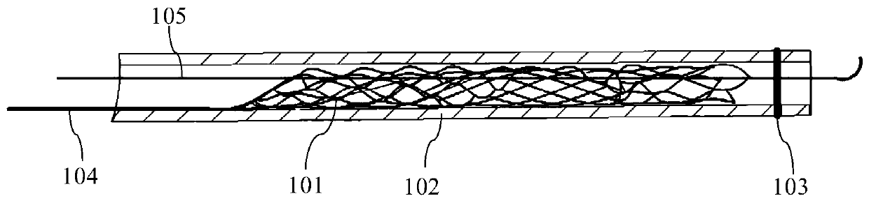
[0063] Such as Figure 4 ~ Figure 8 As shown, a thrombectomy device 300 proposed in this embodiment includes an elongated delivery member 301 and a plurality of thrombectomy members 302 arranged on the elongated delivery member 301. The thrombectomy member 302 has a compressed configuration and a The expanded configuration formed by self-expansion. Each thrombectomy member 302 is assembled on the elongated delivery member 301 to form a thrombectomy functional section of the thrombectomy device 300 . Among the plurality of thrombectomy members 302 on the thrombectomy function section, at least one thrombus retrieval member 302 is rotatably connected to the elongated delivery member 301 .

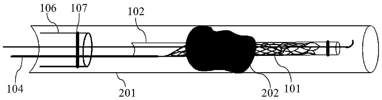
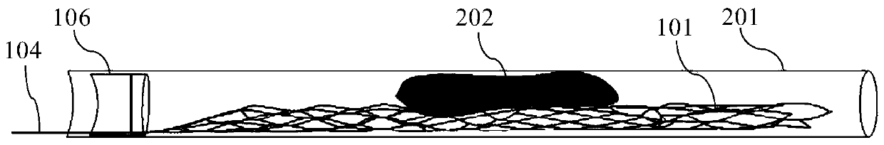
[0064] The thrombectomy device 300 provided in this embodiment can be accommodated in the microcatheter 102 in a compressed configuration. When the thrombus removal operation is performed, the thrombus removal device 300 is sent into the blood vessel 201 through the microcatheter 102 and pas...

Embodiment 2

[0093] The parts of the thrombectomy device 300 in Embodiment 2 that are the same as those in Embodiment 1 will not be repeated here. The main differences between the two are as follows: Figure 34 , Figure 35 As shown, in Embodiment 2, the lattice frame includes a plurality of (for example, two, three, four or more) first support rods 3022 connected to the connector 3021, and the plurality of first support rods 3022 are connected to The connection part of the connector 3021 is used as the starting point to extend in the direction of the distal end in a helically separated manner. The helical direction of each first stent rod 3022 is the same, and the end of each first stent rod 3022 is split into two to separate each other. For the second stent rod 3023 extending in the distal direction, the ends of two adjacent second stent rods 3023 split from different first stent rods 3022 meet at one point.

[0094] In the thrombectomy device 300 of Embodiment 2, since the first bracke...

Embodiment 3

[0099] The parts of the thrombectomy device 300 in Embodiment 3 that are the same as those in Embodiment 1 or Embodiment 2 will not be repeated here. The main differences of Embodiment 3 are as follows: Figure 38 As shown, in Embodiment 3, the thrombectomy member 302 rotatably connected to the elongated delivery member 301 also has a degree of freedom of movement along the axial direction of the elongated delivery member 301 . The connecting piece 3021 is a bush, which is sleeved on the elongated delivery member 301 in a loose fit manner. A guide groove 30211 extending helically from the proximal end to the distal end is provided on the inner wall of the bushing, and a stopper 3013 slidingly fitted with the guide groove 30211 is provided on the elongated delivery member 301 .

[0100] In the thrombectomy device 300 of Example 3, when the elongated delivery member 301 is pushed and pulled during the thrombectomy process, the thrombectomy member 302 with both rotational and mov...


PUM


Abstract

The invention belongs to the field of interventional medical instruments, and particularly relates to a thrombus taking device for taking thrombus out of a blood vessel. The thrombus taking device comprises an elongate delivery member and a plurality of thrombus taking members disposed on the elongate delivery member, wherein the thrombus taking member has a compressed configuration and an expanded configuration formed by self-expansion from the compressed configuration, and at least one of the multiple thrombus taking members is rotatably connected with the elongate delivery member. Accordingto the thrombus taking device, the thrombus taking member has the rotating freedom degree, so that thrombus can enter the thrombus taking member easily through the thrombus inlet, and the thrombus taking member can be fully expanded and make full contact with the thrombus so as to achieve the effective capture of the thrombus.

Description

technical field [0001] The invention belongs to the field of interventional medical devices, and in particular relates to a thrombus removal device for removing thrombus in a blood vessel. Background technique [0002] Stroke is a common disease in medicine. China is a major stroke country in the world, and stroke has become the number one cause of death among Chinese residents. According to relevant epidemiological studies, 3 out of every 4 stroke patients suffer from different degrees of disability. Acute ischemic stroke (AIS, commonly known as cerebral infarction) is the damage of nerve tissue caused by ischemic necrosis of local brain tissue caused by sudden blockage of blood flow in the brain. Acute ischemic stroke is the most common type of stroke and the main cause of death and disability in middle-aged and elderly people. Vascular recanalization is the key to the treatment of acute ischemic stroke. At present, the conventional methods for the treatment of acute i...

Claims


Application Information

Patent Timeline
Patent Type & Authority Applications(China)
IPC IPC(8): A61B17/22
CPCA61B17/22032A61B17/221A61B2017/2215A61B2090/3966A61B2090/3954A61B2017/22045A61B2017/00477A61B2017/22038
Inventor 李思漪
Owner LIFETECH SCI (SHENZHEN) CO LTD
Why Eureka
Try Eureka