Eureka AIR delivers breakthrough ideas for toughest innovation challenges, trusted by R&D personnel around the world.

A thermal power spinning machine unloading mechanism

A technology of powerful spinning and unloading mechanism, used in metal processing equipment, manufacturing tools, stripping devices, etc., can solve problems such as not being able to be easily removed, and achieve the effect of easy wear, unloading problems, and light weight.

Active Publication Date: 2021-08-17
NANCHANG HANGKONG UNIVERSITY
View PDF7 Cites 0 Cited by
  • Summary
  • Abstract
  • Description
  • Claims
  • Application Information

AI Technical Summary

Problems solved by technology

The hot and powerful spinning will also cause the problem that the parts cannot be easily removed after spinning. Therefore, how to design a simple, labor-saving and ingenious mechanism is the key to solving this problem.

Method used

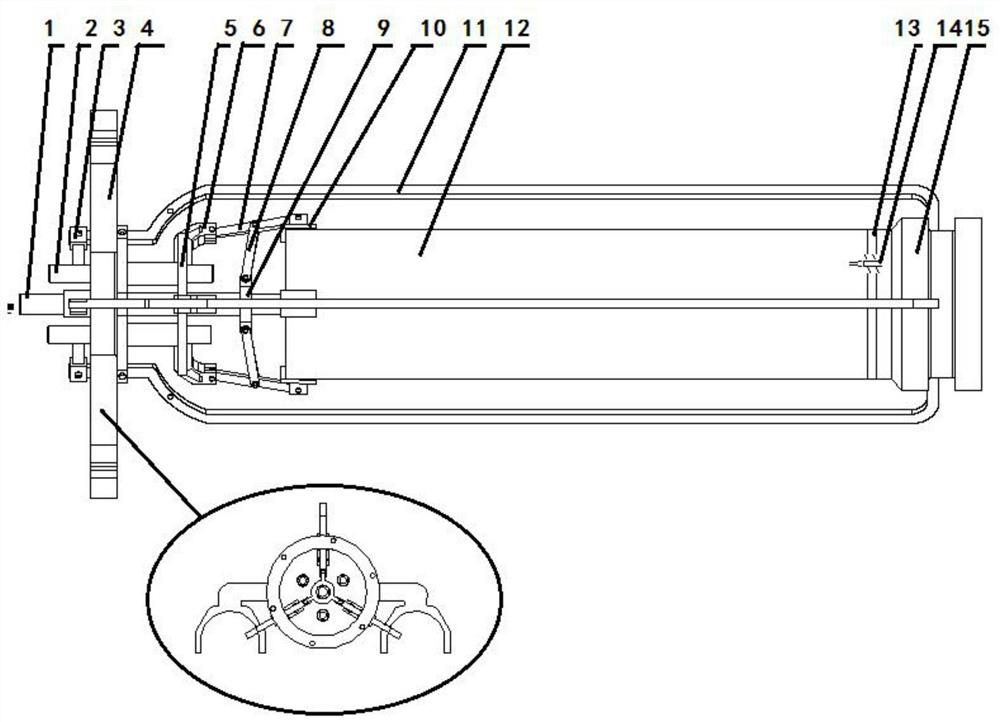
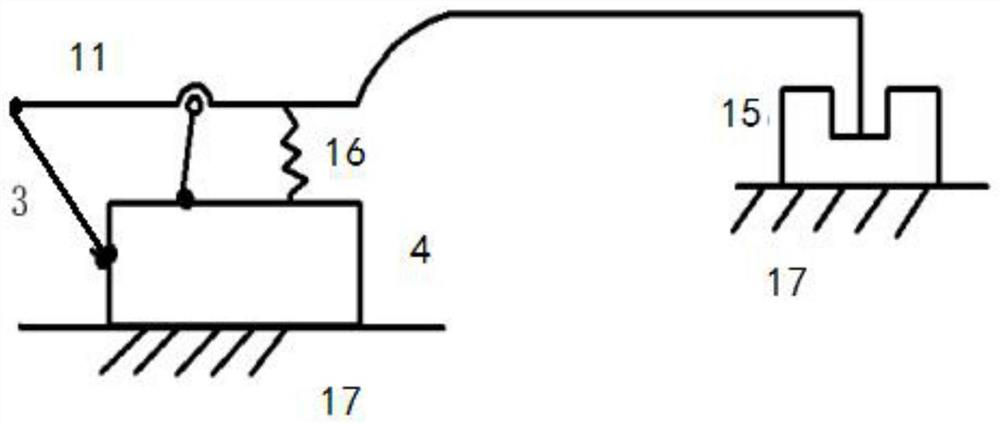
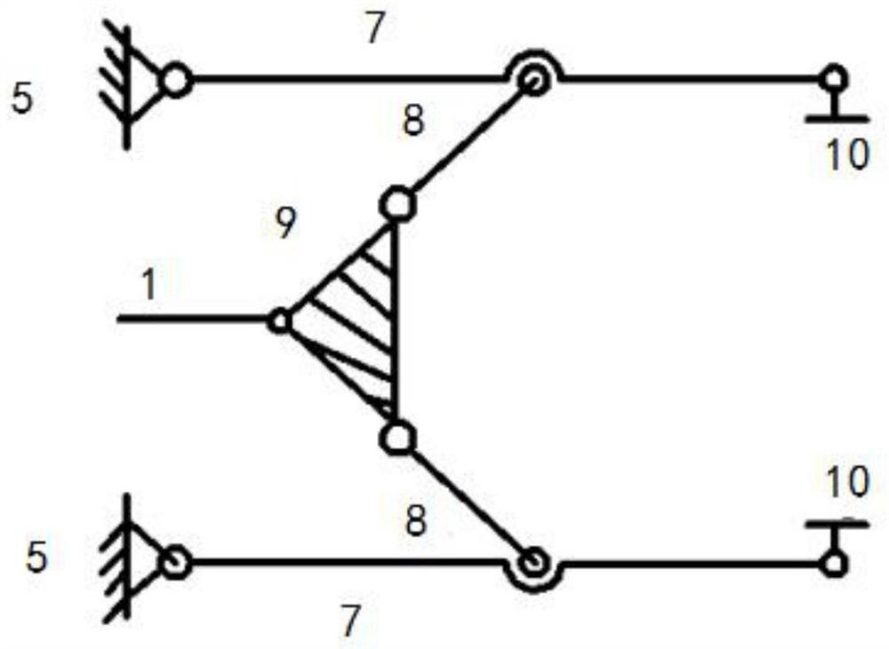

Image

  • A thermal power spinning machine unloading mechanism
  • A thermal power spinning machine unloading mechanism
  • A thermal power spinning machine unloading mechanism

Examples


Embodiment Construction

[0021] The following will clearly and completely describe the technical solutions in the embodiments of the present invention with reference to the accompanying drawings in the embodiments of the present invention. Obviously, the described embodiments are only some, not all, embodiments of the present invention. Based on the embodiments of the present invention, all other embodiments obtained by persons of ordinary skill in the art without making creative efforts belong to the protection scope of the present invention.

[0022] The purpose of the present invention is to provide a thermal power spinning machine unloading mechanism, which can well solve the problem of thermal power spinning machine unloading.

[0023] In order to make the above objects, features and advantages of the present invention more comprehensible, the present invention will be further described in detail below in conjunction with the accompanying drawings and specific embodiments.

[0024] Such as Figu...


PUM


Abstract

The invention discloses a thermal power spinning machine unloading mechanism, which includes a pulling mechanism, a clamping mechanism, and a discharging ring. Installed in the U-shaped groove of the rotary wheel, the pulling force is provided by the movement of the rotary wheel guide rail; the clamping mechanism is similar to a four-bar mechanism, which is mainly composed of a fixed plate, a connecting rod, a ring frame, and a chuck. The nut connected with the frame moves the moving rod left and right, so that the chuck of the clamping mechanism can clamp and loosen the workpiece; the structure of the unloading ring is designed as a combination, and the unloading ring and the cylindrical The parts are connected by multiple stop cones; the advantages of the present invention: the unloading mechanism designed by the present invention is simple in structure and light in weight, which can well solve the unloading problem of the hot and powerful spinning machine; the structural form of the combined unloading ring The disadvantages of the integral unloading ring such as easy wear, complicated design and manufacture, high manufacturing cost and low material utilization rate are solved.

Description

technical field [0001] The invention relates to the technical field of unloading cylindrical parts, in particular to an unloading mechanism of a thermal power spinning machine. Background technique [0002] Thermal force spinning technology is a typical local loading and local forming process, which can spin difficult-to-machine materials with high strength and hardness. It has the advantages of labor saving, material saving and simple tooling. It is the most practical method for manufacturing thin-walled cylindrical parts. One of the effective methods has been widely used in aerospace and weapons industry. The hot and powerful spinning will also cause the problem that the parts cannot be easily removed after spinning. Therefore, how to design a simple, labor-saving and ingenious mechanism is the key to solving this problem. Contents of the invention [0003] The purpose of the present invention is to provide a thermal power spinning machine unloading mechanism, which can...

Claims


Application Information

Patent Timeline
Patent Type & Authority Patents(China)
IPC IPC(8): B21D45/08B21D22/16
CPCB21D22/16B21D45/08
Inventor 赵刚要何龙张冉阳郭正华成一博金郴柏
Owner NANCHANG HANGKONG UNIVERSITY
Why Eureka
Eureka Blog
Learn More