Ground hidden charging pile for new energy vehicles and working method thereof

A technology for new energy vehicles and charging piles, applied in electric vehicle charging technology, charging stations, electric vehicles, etc., can solve the problems of charging piles entering water, damage to electronic parts, shortening the service life of charging piles, etc. The effect of drying, prolonging the service life, avoiding the damage and failure of the charging pile and shortening the service life

Active Publication Date: 2021-08-03
CHANGZHOU INST OF DALIAN UNIV OF TECH
View PDF9 Cites 0 Cited by
  • Summary
  • Abstract
  • Description
  • Claims
  • Application Information

AI Technical Summary

Problems solved by technology

[0004] The purpose of the present invention is to solve the problem that most of the existing charging piles are installed on the ground and will be exposed to the sun and rain for a long time, which will lead to accelerated aging of the casing of the charging pile and excessive temperature of the casing will damage the internal electronic components. The components are damaged, the rain will cause water to enter the charging pile, and there is a short circuit during the charging process, which shortens the service life of the charging pile, and the maintenance of the charging pile is not convenient enough, and the protection effect is not good enough. Ground hidden charging pile for new energy vehicles and working method thereof

Method used


Image

  • Ground hidden charging pile for new energy vehicles and working method thereof
  • Ground hidden charging pile for new energy vehicles and working method thereof
  • Ground hidden charging pile for new energy vehicles and working method thereof

Examples


Embodiment Construction

[0040] The technical solutions of the present invention will be clearly and completely described below in conjunction with the embodiments. Apparently, the described embodiments are only some of the embodiments of the present invention, not all of them. Based on the embodiments of the present invention, all other embodiments obtained by persons of ordinary skill in the art without creative efforts fall within the protection scope of the present invention.

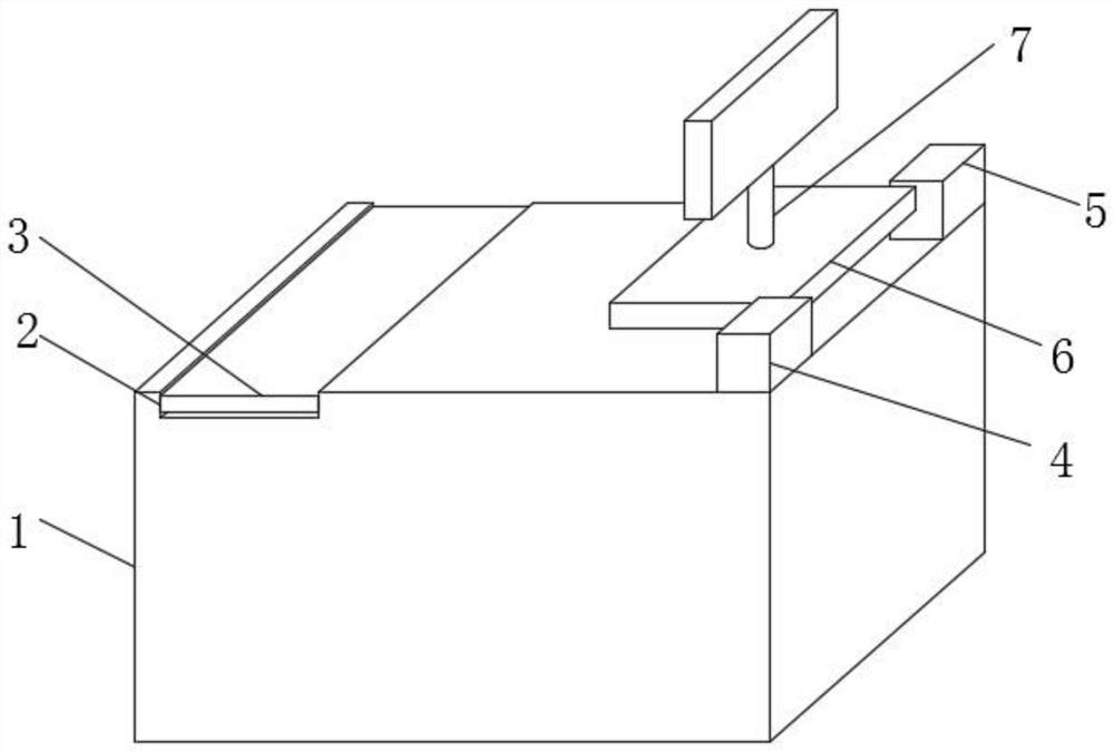
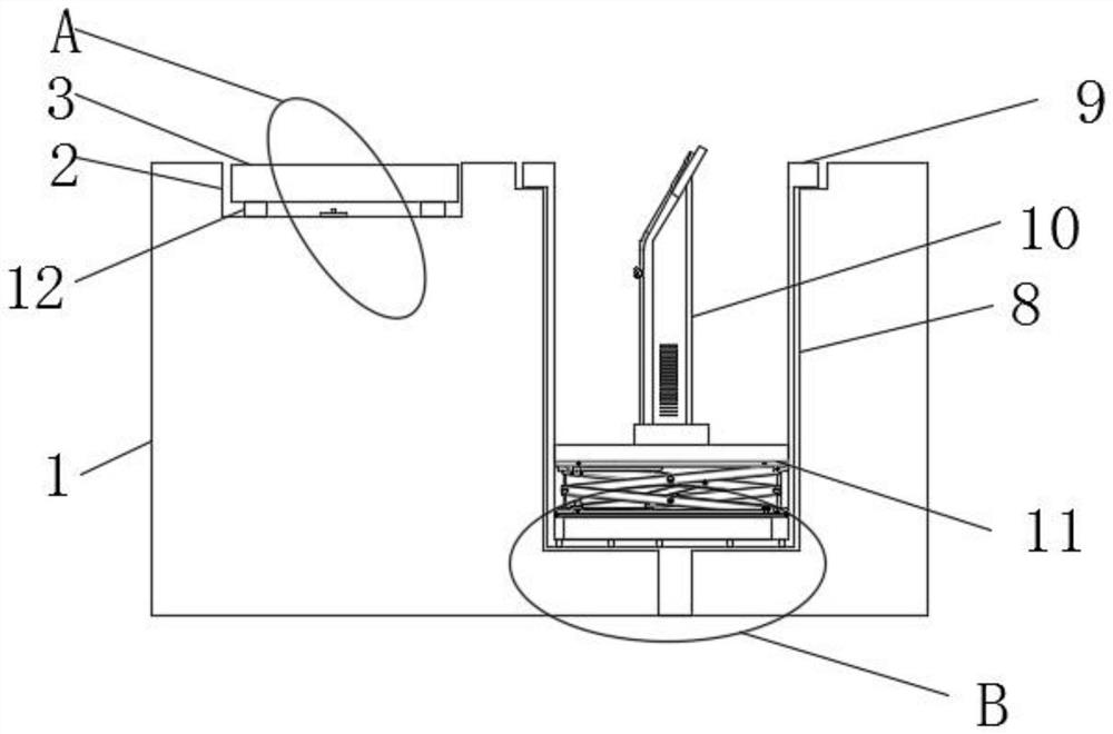
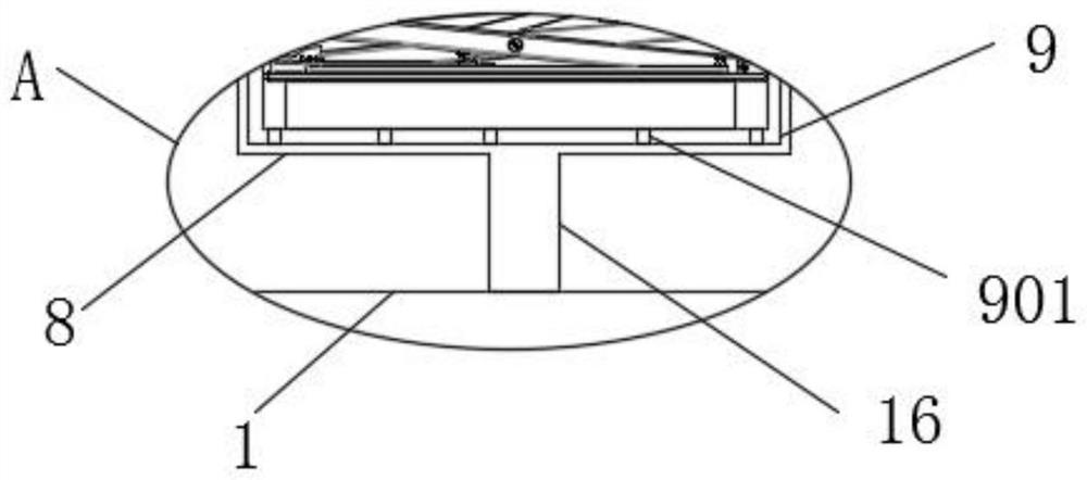
[0041] see Figure 1-10 As shown, a ground hidden charging pile for new energy vehicles includes a pre-embedded box body 1 and a charging pile body 10. The interior of the pre-embedded box body 1 is provided with a preset cavity 8, and the interior of the preset cavity 8 is inserted The load-bearing box 9 is connected, and the charging pile body 10 is arranged inside the load-bearing box 9. A pressure groove 2 is opened on the outer surface of the upper end of the pre-embedded box body 1, and a pressure plate 3 is embedded ...


PUM


Abstract

The invention discloses a ground hidden charging pile for new energy vehicles and a working method thereof, which comprises a pre-embedded box body and a charging pile body. A load-bearing box is plugged into the body, the charging pile body is set inside the load-bearing box, a pressure groove is opened on the outer surface of the upper end of the pre-embedded box, and a pressure plate is embedded in the inside of the pressure groove, and the pre-embedded box The outer surface of the upper end of the body away from the side of the pressure groove is bolted to the brake box and the mounting seat, the position between the brake box and the mounting seat is provided with a cover, and the outer surface of the upper end of the cover is welded with an identification plate , the inside of the brake box is provided with a brake motor; the inner bottom of the load-bearing box is provided with a hydraulic lifting platform; the present invention can reduce the time for the charging pile to be exposed to the sun and rain through the hidden setting, and the maintenance It is easy to maintain and prolongs the service life of the charging pile, making the charging pile more worthy of promotion and use.

Description

technical field [0001] The invention relates to a charging pile, in particular to a ground hidden charging pile for new energy vehicles and a working method thereof, belonging to the technical field of charging new energy vehicles. Background technique [0002] The Chinese invention patent with the notification number CN107351718B discloses a charging pile for electric vehicles, including a charging pile body, a charging pile protective cover is arranged above the charging pile body, and a protective cover is provided on the front surface of the charging pile protective cover. Baffle, and the front surface of the protective cover of the charging pile is provided with a baffle rotating shaft close to the inside of the folding baffle of the protective cover, and the adjacent folding baffles of the protective cover are connected through the rotation of the baffle rotating shaft. A charger slide rail is provided, and the charging pile body and the charger slide rail are fixedly ...

Claims


Application Information

Patent Timeline
Patent Type & Authority Patents(China)
IPC IPC(8): B60L53/31B60L53/30
CPCB60L53/30B60L53/31Y02T10/70Y02T10/7072Y02T90/12
Inventor 罗水英
Owner CHANGZHOU INST OF DALIAN UNIV OF TECH
Why Eureka
Try Eureka