Vertical brush of car washer

A car washing machine and vertical brush technology is applied in the field of car washing machines to achieve the effects of ensuring smooth lifting, improving cleaning performance, and improving fluency

Pending Publication Date: 2020-06-12
宁波昊天智能设备科技有限公司
View PDF0 Cites 1 Cited by
  • Summary
  • Abstract
  • Description
  • Claims
  • Application Information

AI Technical Summary

Problems solved by technology

Existing vertical brushes generally include a vertically arranged rotating roller, a cleaning brush fixed on the outer ring wall of the rotating roller, and a drive mechanism that drives the rotating roller to rotate after the upper end of the rotating roller co

Method used


Image

  • Vertical brush of car washer
  • Vertical brush of car washer
  • Vertical brush of car washer

Examples


Embodiment 1

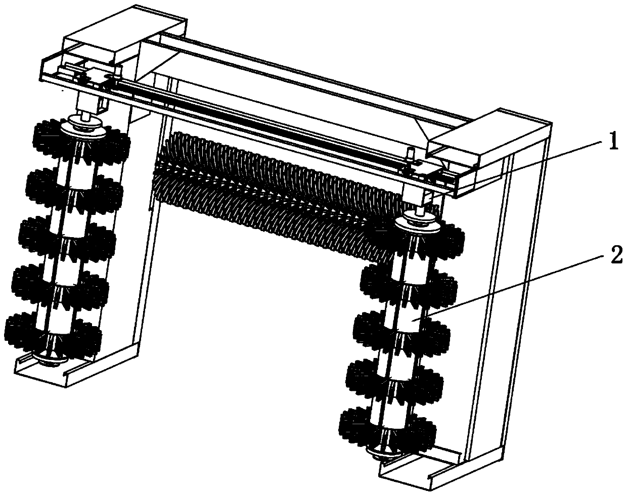
[0028] A kind of vertical brush of car washing machine, refer to Figure 1-Figure 5 As shown, it includes a vertically arranged rotating roller, a cleaning brush assembly arranged on the outer ring wall of the rotating roller to rotate synchronously with the rotating roller, and a servo motor 1 that drives the rotating roller to rotate.

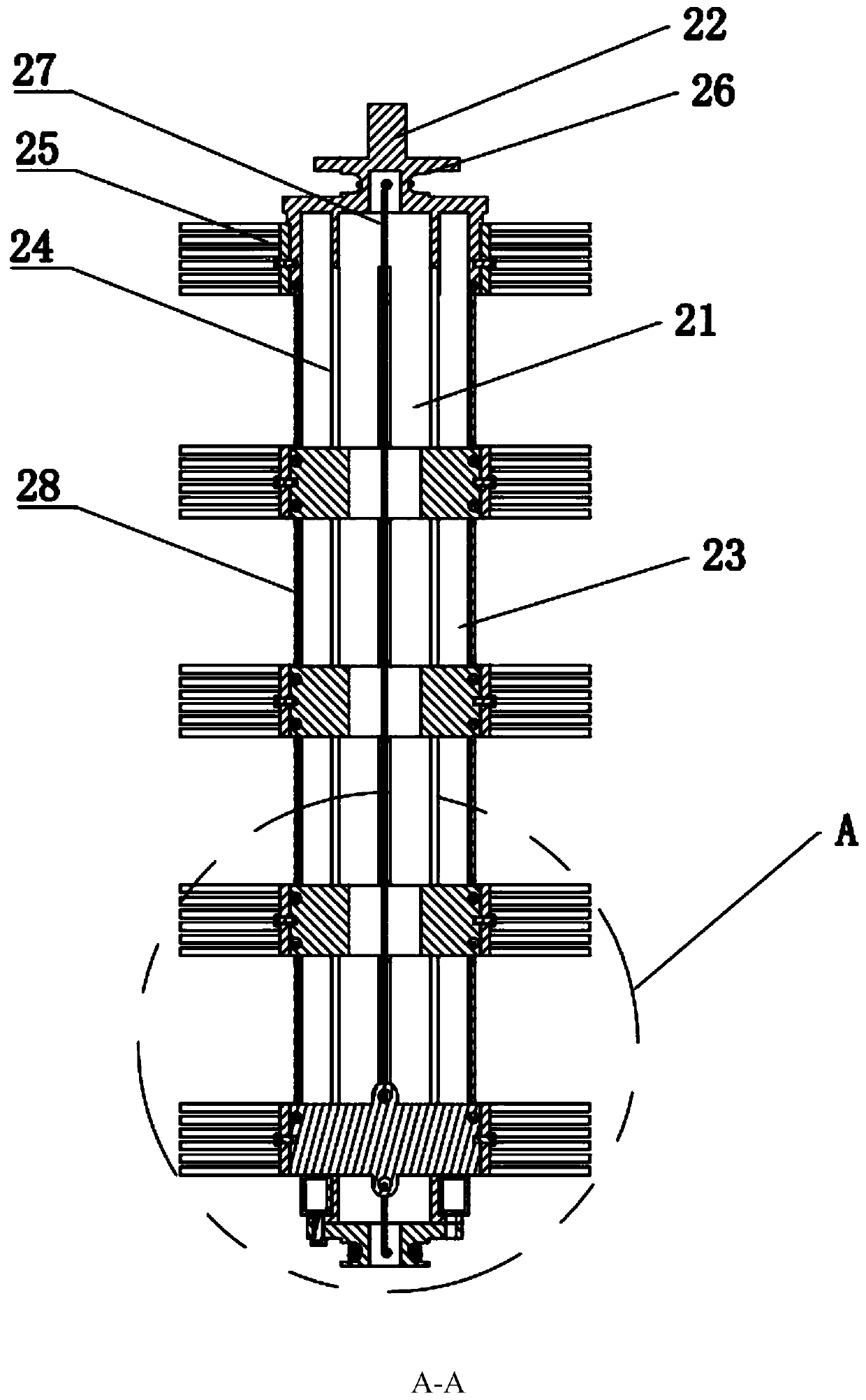
[0029] Refer to the specific structure of the rotating roller Figure 2-Figure 5 As shown, it includes a hollow roller body 21 and a rotating shaft 22 whose upper end of the roller body 21 is fixed with the motor shaft key of the servo motor 1. On the outer ring wall of the roller body 21, there are several directions distributed around the axial interval of the roller body 21. An axially extending guide channel of the roller body 21 .

[0030] Cleaning brush assembly specific reference Figure 3-Figure 4 As shown, it includes a number of lifting blocks distributed longitudinally at intervals inside the roller body 21, a guide block 212 int...

Embodiment 2

[0037] On the basis of embodiment 1, the improvement of this embodiment refers to Figure 3-Figure 5 As shown: a linkage connection structure is provided between adjacent guide blocks 212, and the linkage connection structure is a second stay rope 28 that is detachably arranged between the upper and lower guide blocks 212, and the opposite end of the guide block 212 is provided with a The threading holes 213 through which the two stay cords 28 pass.

[0038] The arrangement of the second pull cord 28 enables the adjacent cleaning brush bodies 25 to be in linkage connection, so the stuck phenomenon that may be caused by the driven lifting block 211 falling only by gravity can be avoided.

Embodiment 3

[0040] On the basis of embodiment 2, the improvement of this embodiment refers to Figure 3-Figure 4 As shown: an airbag layer 23 is provided on the outer ring wall of the roller body 21. After the airbag layer 23 is inflated, it fits or gaps with the fixed sleeve, and the airbag layer 23 is provided with an air nozzle for easy inflation or deflation.

[0041] Setting the airbag layer 23 can reduce the degree of damage caused by the vertical brush 2 or the car's operation error causing the car to directly contact the hard roller body 21 or avoid damage, and at the same time increase safety.


PUM


Abstract

The invention relates to the field of car washers. The invention discloses a vertical brush of a car washer. The vertical brush comprises a rotating roller, a cleaning brush assembly and a servo motordriving the rotating roller to rotate. The rotating roller comprises a roller body and a rotating shaft; a plurality of guide through grooves extending in the axial direction of the roller body are distributed in the outer ring wall of the roller body around the axial direction of the roller body at intervals. The cleaning brush assembly comprises a plurality of lifting blocks longitudinally distributed in the roller body at intervals, guide blocks integrally extending from the lifting blocks to the exteriors of the guide through grooves, and cleaning brush bodies located outside the roller body and fixed to the ends, away from the lifting blocks, of the guide blocks. The lifting block located at the lowermost end is a solid active lifting block. The other lifting blocks are driven lifting blocks with center holes, the upper end and the lower end of the roller body are provided with driving structures which drive the cleaning brush body to do lifting motion while rotating along with forward and reverse rotation of the servo motor, the vertical brush of the car washer can improve the overall running process, the cleaning performance is effectively improved, and great increase of the manufacturing cost is avoided.

Description

technical field [0001] The invention relates to the field of car washing machines, in particular to a vertical brush of a car washing machine. Background technique [0002] The car washing machine is mainly a machine that uses computer-controlled brushes and high-pressure water to automatically clean cars. It is mainly composed of control system, circuit, air circuit, water circuit and mechanical mechanism. [0003] The mechanical mechanism includes a movable support, on which a brush assembly is arranged, and the brush assembly includes a vertical brush mechanism, a horizontal brush mechanism and a wheel brush mechanism. [0004] Existing vertical brush mechanism comprises a beam, two vertical brushes that move horizontally and are arranged on the beam. Existing vertical brushes generally include a vertically arranged rotating roller, a cleaning brush fixed on the outer ring wall of the rotating roller, and a drive mechanism that drives the rotating roller to rotate after...

Claims


Application Information

Patent Timeline
IPC IPC(8): B60S3/06
CPCB60S3/063
Inventor 冉永亮
Owner 宁波昊天智能设备科技有限公司
Why Eureka
Try Eureka