Moving bed reaction furnace for producing sponge iron by direct reduction of gas base

A technology of sponge iron and reaction furnace, which is applied in the direction of hearth furnace, furnace, furnace type, etc., can solve the problems of high dust content, coking and clogging of solid materials, etc., to reduce dust content, prevent coking and clogging, and avoid bed The effect of sintering

Pending Publication Date: 2020-06-12
上海泰普星坦新材料有限公司
View PDF0 Cites 0 Cited by
  • Summary
  • Abstract
  • Description
  • Claims
  • Application Information

AI Technical Summary

Problems solved by technology

[0004] The purpose of the present invention is to provide a moving bed reaction furnace for the production of sponge iron by gas-based direct reduction in view of the technical defects of the existing gas-based direct reduction production of sponge iron. The reaction furnace is designed by the large diameter and height of the upper slightly

Method used


Image

  • Moving bed reaction furnace for producing sponge iron by direct reduction of gas base
  • Moving bed reaction furnace for producing sponge iron by direct reduction of gas base
  • Moving bed reaction furnace for producing sponge iron by direct reduction of gas base

Examples


Embodiment 1

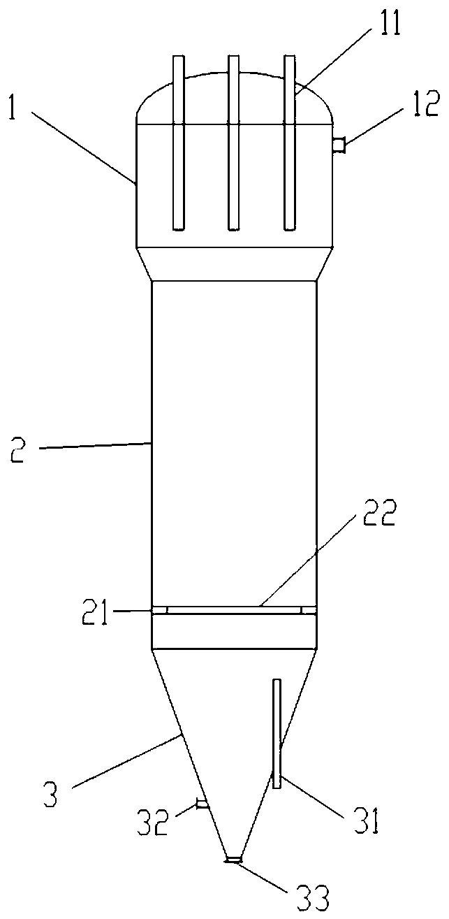
[0036] A moving bed reactor for the production of sponge iron by gas-based direct reduction, the structure of which is as follows figure 1 As shown, the whole is a vertical cylindrical structure, which consists of the upper slightly enlarged head section 1, the middle cylinder section 2 and the lower cone section 3 connected in sequence from top to bottom. The specific structure and function of each part are as follows:

[0037]The upper part of the micro-enlarging head section 1 is provided with an exhaust gas outlet 12 for discharging reaction exhaust gas; the top is provided with a solid material uniform distribution chute 11, and solid materials such as iron oxide pellets enter the reaction furnace along the solid material uniform distribution chute 11. The reduction reaction is carried out in the reaction furnace, preferably 4 to 12 solid material uniform distribution chute 11, more preferably 6, to ensure that the charge is more evenly distributed in the furnace body; the...

Embodiment 2

[0042] A moving bed reaction furnace for gas-based direct reduction to produce sponge iron, which is a further refinement of some options in Example 1, and is used for gas-based direct reduction to produce sponge iron in a moving bed reaction furnace for processing iron oxide pellets , the furnace body design of the moving bed reactor and the reaction process in it are:

[0043] The shell of the reaction furnace is made of GH474 high-temperature steel, and the interior is coated with a composite high-temperature resistant coating mainly composed of corundum. The iron oxide pellets are fed into the reaction furnace from the micro-expansion head section 1 top of the reaction furnace, and the reduction reaction is completed in the reaction furnace. The number of solid material uniform distribution pipes 11 is 6.

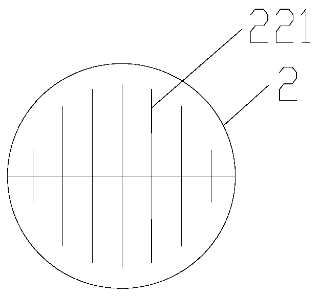
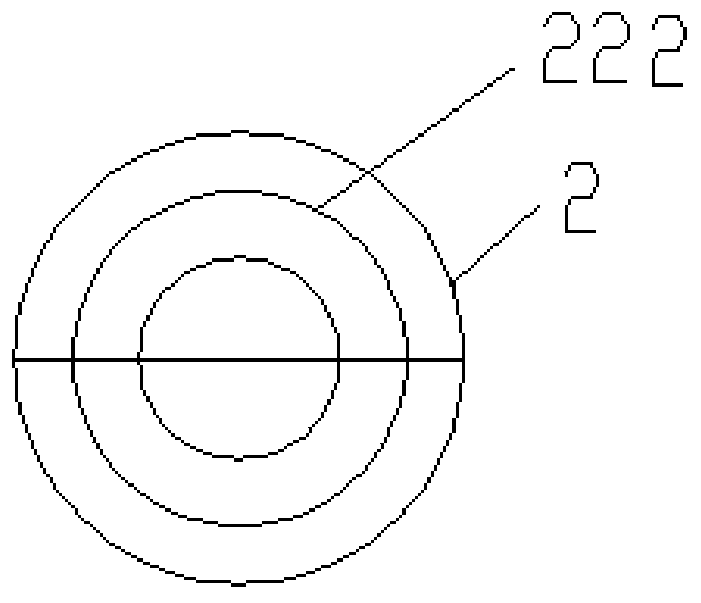
[0044] The high-temperature reducing gas enters the gas distributor 22 from the reducing gas inlet 21 of the cylinder section 2 in the middle of the reaction furnace, a...


PUM


Abstract

The invention provides a moving bed reaction furnace for producing sponge iron by direct reduction of a gas base. The moving bed reaction furnace comprises a slightly expanded upper large head section(1), a middle cylinder section (2) and a lower cone section (3) which are connected in sequence from top to bottom in a furnace body height direction; the slightly expanded upper large head section is provided with an exhaust outlet (12) and a solid material uniform distributing sliding pipe (11); exhaust gas dust entrainment is reduced by the slightly expanded upper large head section; the middle cylinder section is provided with a reducing gas inlet (21) and a gas distributor (22); the gas distributor achieves gas distributing and solid material rectifying effects; the lower cone section is provided with a cooling gas inlet (32), a solid material outlet (33) and a vertical spiral loosing device (31); low-temperature solid material discharging is realized in the cooling gas inlet; afterheat of a solid material is realized; the vertical spiral loosing device realizes axial circulating and radial rotating movement of a solid material on a bed layer; sintering of a bed layer is thoroughly avoided; and smooth discharging at an outlet is ensured.

Description

technical field [0001] The invention belongs to the technical field of metallurgical equipment, and in particular relates to a moving bed reaction furnace for gas-based direct reduction to produce sponge iron. Background technique [0002] With the rapid development of the world's steel industry and the increasing attention paid by the international community to environmental protection, direct reduced iron technology has received more and more attention from the steel industry, and the demand for direct reduced iron has grown strongly. In 2018, the global direct reduced iron production breakthrough 100 million tons. [0003] Gas-based direct reduction processes for producing sponge iron mainly include Midrex and HYL. First of all, due to the high dust content in the furnace top exhaust gas in the existing process, the load of the subsequent cooling and dust removal process is increased; secondly, the reducing gas directly enters the reaction furnace from the cylinder witho...

Claims


Application Information

Patent Timeline
IPC IPC(8): C21B13/10
CPCC21B13/0073C21B13/105
Inventor 王金福任立军薛健靳辉
Owner 上海泰普星坦新材料有限公司
Why Eureka
Try Eureka