
Vibration chamber flange plate and vibration mechanism of vibration wheel of extra-heavy vibratory roller

A technology of vibratory roller and vibrating mechanism, applied in the direction of road, road, road repair, etc., can solve the problems of poor operation safety and reliability, damage to other parts, easy damage of spline shaft, etc., so as to improve the cooling and lubrication effect and work reliably. , The effect of improving work reliability

Pending Publication Date: 2020-06-12
SINOMACH CHANGLIN CO LTD
View PDF0 Cites 0 Cited by
  • Summary
  • Abstract
  • Description
  • Claims
  • Application Information

AI Technical Summary

Problems solved by technology

In the existing vibration chamber, after the inner and outer flanges are combined, the end faces of the inner and outer flanges are fixed together on the vibration spoke plate with bolts. When repairing or replacing the spline shaft, the outer flange needs to be removed. During the disassembly process , there is no fixed connection between the inner and outer flanges and the vibration wheel spoke plate, it is easy to bring down the relevant components in the vibration chamber together, which is easy to cause damage to other components, which is labor-intensive and time-consuming, and the operation safety and reliability are poor
Especially for ultra-heavy vibratory rollers above 24 tons, due to the relatively greater vibration force, the coupling sleeve and spline shaft that bear the impact load are more likely to be damaged, and the maintenance cost of the spline shaft and the safety of replacement after wear and tear have always been the key Troubled the manufacturer, but also the focus of feedback from repairers and users

Method used


Image

  • Vibration chamber flange plate and vibration mechanism of vibration wheel of extra-heavy vibratory roller
  • Vibration chamber flange plate and vibration mechanism of vibration wheel of extra-heavy vibratory roller
  • Vibration chamber flange plate and vibration mechanism of vibration wheel of extra-heavy vibratory roller

Examples


Embodiment Construction

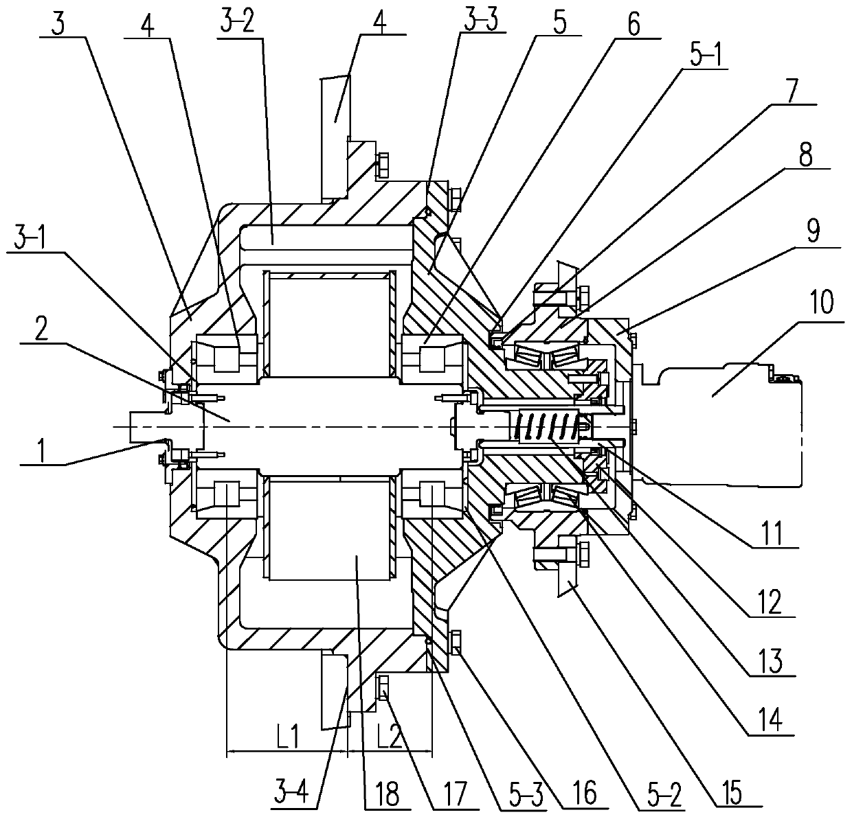
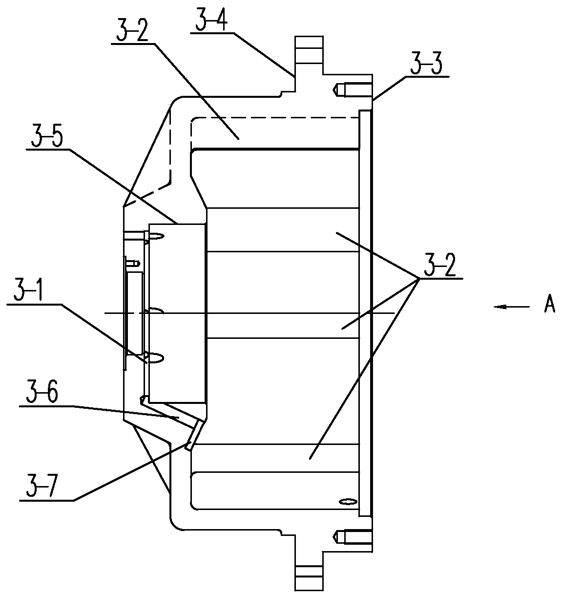
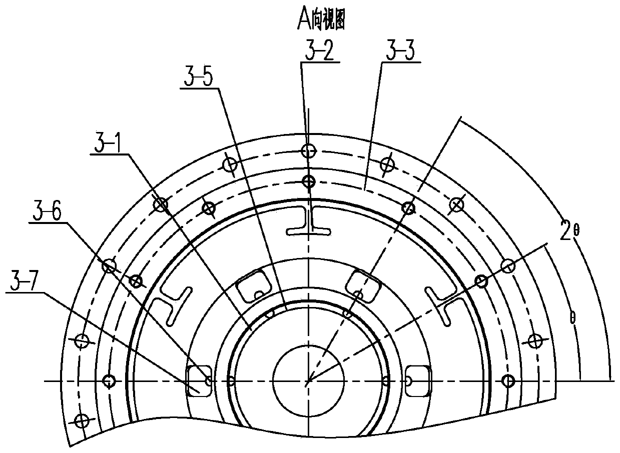
[0017] See Figure 1-6 As shown, the vibration chamber flange of the present invention includes an inner flange 3 provided with a first bearing hole 3-5 and an outer flange 5 provided with a second bearing hole 5-6, and the inner flange of the sealed connection The disc 3 and the outer flange 5 form a vibration chamber.

[0018] See Figure 1-6 As shown, the inner flange 3 of the present invention has an inner flange connection surface 3-4 connected to the vibrating spoke plate 4 and a stepped first joint surface 3-4 connected to the outer flange 5 with installation positions staggered. 3. Outer flange connection bolts 17 connect the inner flange 3 with the vibrating spoke plate 4, and connect the vibration chamber to the vibrating spoke plate 4 through the inner flange 3, since the outer flange 5 is no longer connected to the vibrating spoke plate 4 The spoke plate 4 is connected, so when the outer flange 5 is removed, the inner flange 3 is fixed on the vibrating spoke plat...


PUM


Abstract

The invention relates to a vibration chamber flange plate. The vibration chamber flange plate comprises an inner flange plate and an outer flange plate which are mutually connected, wherein the innerflange plate is provided with an inner flange connecting surface and a first joint surface which are staggered in mounting position; a plurality of T-shaped rib plates extending towards the rotating center and a plurality of first inclined oil ducts uniformly distributed on one side of a first bearing hole are uniformly distributed on the axial inner wall of the inner flange plate, one end of eachfirst inclined oil duct is communicated with the inner side surface of the plate wall, and the other end of each first inclined oil duct is communicated with the inner end surface of the first bearing hole; the outer flange plate is provided with a second joint surface matched with the first joint surface and a plurality of second inclined oil ducts uniformly distributed on one side of a second bearing hole, one end of each second inclined oil duct is communicated with the inner side surface of the plate wall, and the other end is communicated with the outer end surface of the second bearinghole; and the T-shaped rib plates are respectively staggered with the first inclined oil ducts and the second inclined oil ducts. According to the invention, the heat balance temperature of the vibration chamber can be effectively reduced, the working reliability and the overhaul and maintenance safety are improved, and the maintenance and use cost of a user can be reduced.

Description

technical field [0001] The invention relates to a flange plate of a vibrating chamber and a vibration mechanism of a vibrating wheel of a super-heavy vibratory road roller, belonging to the technical field of super-heavy vibratory road rollers. Background technique [0002] The vibrating wheel vibrating mechanism of heavy-duty vibratory roller mainly includes two types of parts, the vibrating unit part that generates the exciting force and the connecting part that transmits the power, which mainly includes two independent vibrating chambers, a vibrating motor and a connection between the two vibrating chambers and the vibrating motor and other parts. The vibration chamber usually uses the connected inner and outer flanges and the eccentric components in the inner and outer flanges. A small amount of lubricating oil is injected into the cavity of the closed vibration chamber. When the vibration is working, the vibration bearings at both ends of the vibration shaft are lubrica...

Claims


Application Information

Patent Timeline
IPC IPC(8): E01C19/28
CPCE01C19/28E01C19/286
Inventor 沈志龙李靖
Owner SINOMACH CHANGLIN CO LTD
Learn More