Plunger type water pump

A plunger type and water pump technology, applied in the field of plunger type water pumps and volumetric hydraulic pumps, can solve the problems of pollution sensitivity, low power-to-weight ratio, oil pollution, etc., achieve reduced use costs, low heat balance temperature, and solve environmental pollution Effect

Active Publication Date: 2012-07-04
HUAZHONG UNIV OF SCI & TECH
View PDF0 Cites 0 Cited by
  • Summary
  • Abstract
  • Description
  • Claims
  • Application Information

AI Technical Summary

Problems solved by technology

[0005] 1. The maximum working pressure is 16MPa, which does not meet the needs of special occasions, such as the requirements of the buoyancy adjustment system of manned submersibles at large depths (diving depths greater than 3000 meters)
[0006] 2. The distribution plate is used for flow distribution. On the one hand, it is sensitive to pollution and is not suitable for use in open systems. On the other hand, it is difficult to ensure the volumetric efficiency after high pressure.
[0009] 1) The speed is low (100-500rev / min), large in size and low in power-to-weight ratio; if the speed is increased, the volume of the pump can be reduced, but the seal between the water chamber and the lubricating oil chamber will heat up severely and easily fail. Especially in the case of high pressure, this situation will be exacerbated; at the same time, the temperature of the oil in the sealed lubricating oil chamber will also increase due to poor heat dissipation, which will cause the oil to deteriorate
[0010] 2) It needs to be lubricated with oil, which will inevitably cause oil pollution. In addition, when it is used in a deep sea environment, a pressure compensation device needs to be added, which makes its overall structure complicated

Method used


Image

  • Plunger type water pump
  • Plunger type water pump
  • Plunger type water pump

Examples


Embodiment Construction

[0036] The present invention will be further described below in conjunction with the accompanying drawings and embodiments.

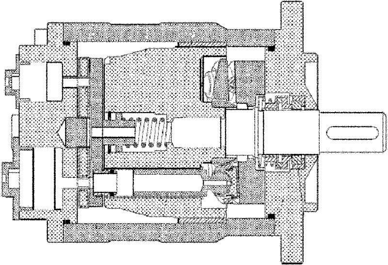
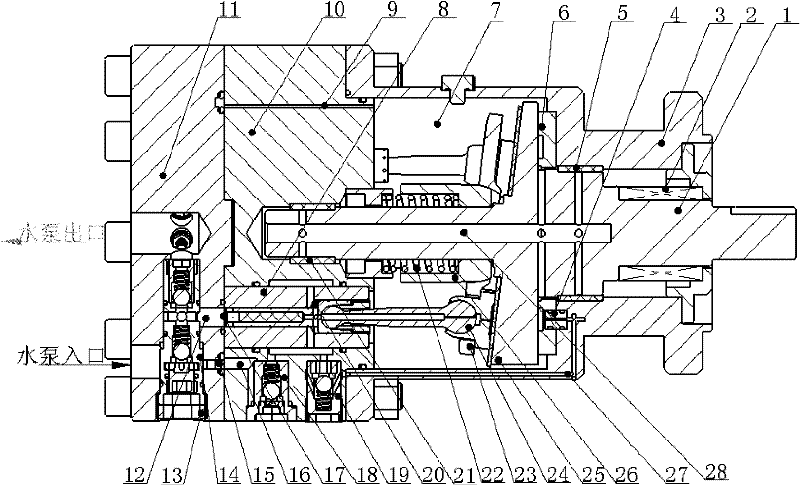
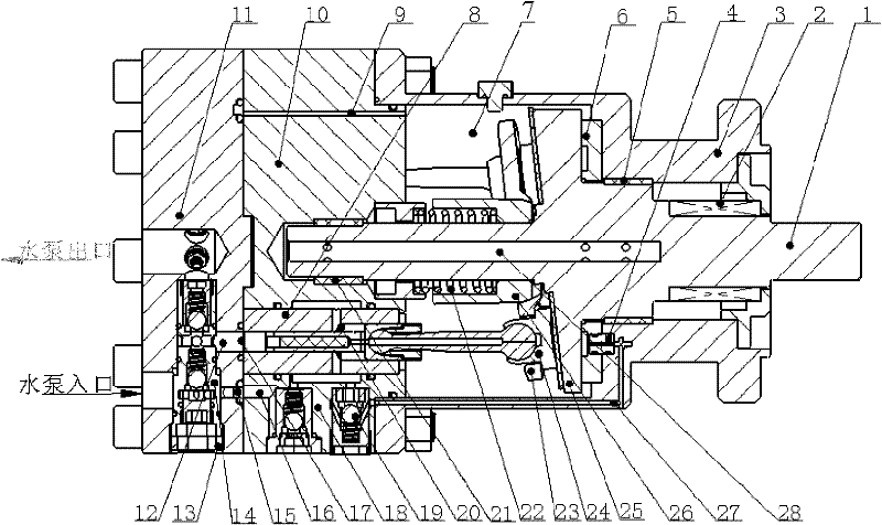
[0037] A schematic structural diagram of a plunger water pump according to an embodiment of the present invention is shown in FIG. 2 . The plunger water pump includes modules such as a pump main body, a rotating unit, and a plunger flow distribution unit. Wherein, the pump main body includes a cavity, a water pump inlet and a water pump outlet. The rotary unit comprises a rotary spindle 1 . The plunger distribution unit mainly includes a plunger shoe assembly 24 , a distribution valve assembly 14 and a supporting valve assembly. Wherein the support valve assembly includes a support suction valve 18 and a support discharge valve 19 . The plunger shoe assembly 24 is arranged in the cavity, and the cavity is divided into a high-pressure chamber 17, a low-pressure chamber 20 and a lubricating chamber 7 which are independent of each other. The supporting ...


PUM


Abstract

The invention provides a plunger type water pump which mainly comprises a cavity body, a rotary main shaft and a plunger distributing unit, wherein the plunger distributing unit comprises a distributing valve assembly, a plunger piston shoe assembly and a supporting valve assembly; the plunger piston shoe assembly divides the cavity body into a high-pressure cavity and a low-pressure cavity mutually independent; the high-pressure cavity is communicated with the liquid of the distributing valve assembly; and the low-pressure cavity is communicated with the liquid of the supporting valve assembly. The plunger piston shoe assembly driven by the rotary main shaft reciprocates to impel the distributing valve assembly and the supporting valve assembly to cooperate, thus the distributing valve assembly sucks and discharges water through a water pump inlet and a water pump outlet, and simultaneously the supporting valve assembly provides liquid lubrication for the rotary unit. High-pressure water output by the extra-high pressure pump of the invention is mutually independent of the low-pressure water used for static pressure supporting and lubrication, thus ensuring the volumetric efficiency of the water pump in the extra-high pressure condition, ensuring the liquid supporting and lubrication of a friction pair in a high-speed heavy-load condition, and improving the service life of the water pump.

Description

technical field [0001] The present invention relates to a positive displacement hydraulic pump, in particular to a plunger type water pump, more specifically to a full water lubricated ultra-high pressure plunger type water pump. Background technique [0002] With the emergence of the world's energy crisis and the improvement of people's awareness of environmental protection, as well as the special physical and chemical characteristics of the water medium itself, water hydraulic technology has the inability of oil pressure systems in many fields (such as underwater operations, buoyancy adjustment of manned submersibles, etc.). Compared with the advantages, so that the water hydraulic technology has been developed rapidly. [0003] However, since the viscosity of water is about 1 / 30 to 1 / 50 of that of commonly used hydraulic oil, it is difficult to form a water film, and the lubricity is poor. At the same time, due to the strong corrosion of water, especially seawater, the ch...

Claims


Application Information

Patent Timeline
Patent Type & Authority Patents(China)
IPC IPC(8): F04B1/16F04B53/00
Inventor 刘银水吴德发蒋卓贺小峰朱碧海郭志恒毛旭耀陈经跃
Owner HUAZHONG UNIV OF SCI & TECH
Why Eureka
Try Eureka