
Sand discharge funnel

A funnel and flow regulating technology, which is applied in the field of sand discharge funnel and sediment secondary treatment facilities, can solve the problems of sedimentation at the bottom of the funnel chamber, sedimentation of hanging plate sedimentation and water consumption rate, etc. The effect of small circumference and large flow rate

Active Publication Date: 2020-06-12
XINJIANG AGRI UNIV
View PDF4 Cites 2 Cited by
  • Summary
  • Abstract
  • Description
  • Claims
  • Application Information

AI Technical Summary

Problems solved by technology

[0007] Technical problem: When the existing sand discharge funnel handles high-concentration sandy water mainly composed of fine particles, there will be serious sediment deposition at the bottom of the funnel chamber, serious sediment deposition on the suspension plate, and high water consumption rate for sand discharge

Method used


Image

  • Sand discharge funnel
  • Sand discharge funnel
  • Sand discharge funnel

Examples


Embodiment

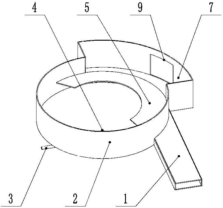
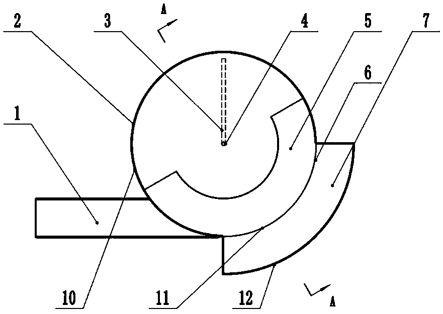
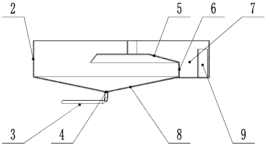
[0022] The sand discharge funnel of present embodiment is as figure 1 , figure 2 with image 3 As shown, the water inlet culvert 1, the side wall 2, the funnel chamber 8, the flow regulating suspension plate 5, the overflow weir 6 and the side groove 7 are included, and the water inlet culvert 1 is connected to the upper part of the funnel chamber 8, and is connected to the top of the funnel chamber 8. The outer circumference is tangent, the bottom of the funnel chamber 8 is provided with a sand discharge bottom hole 4, the sand discharge bottom hole 4 is connected with a sand discharge corridor 3, and the side wall 2 is connected to the upper part of the funnel chamber 8 to form a first circular arc section surrounding structure 10, The overflow weir 6 is connected to the upper part of the funnel chamber 8 to form a second circular arc segment surrounding structure 11. The height of the overflow weir 6 is lower than that of the side wall 2. The flow-regulating suspension pl...


PUM


Abstract

The invention provides a sand discharge funnel. The sand discharge funnel comprises a water inlet culvert, an edge wall, a funnel chamber, a flow adjusting suspension plate, an overflow weir and a side groove; the water inlet culvert is connected to the upper portion of the funnel chamber, and is tangential to the outer periphery of the funnel chamber; and a sand discharge bottom hole is formed inthe bottom of the funnel chamber, and is connected to a sand discharge gallery. The edge wall is connected to the upper portion of the funnel chamber to form a first arc section envelope structure. The overflow weir is connected to the upper portion of the funnel chamber to form a second arc section envelope structure. The flow adjusting suspension plate is provided with a center-near end and a center-far end; the center-far end is connected to the upper end of the overflow weir; and the center-near end is near the center of the funnel chamber and higher than the center-far end. The side groove is connected to one side of the overflow weir to form a third arc section envelope structure with the edge wall; and a drainage ditch port is formed in the side groove. Through structural improvement, the problems of bad sediment accumulation at the bottom of the funnel chamber and on the suspension plate and high sand discharge water consumption rate are solved, and the sand discharge efficiency of the sand discharge funnel is improved.

Description

technical field [0001] The invention belongs to the technical field of water conservancy engineering, and relates to a sediment secondary treatment facility, in particular to a sand discharge funnel. Background technique [0002] Rivers often contain a lot of silt, especially in northern rivers, not only the silt content is high, the silt particles are also very fine, and the suspended sediment content is high. With the rapid development of production, the requirements for the quantity and quality of diverted water are getting higher and higher. Sand discharge funnel (that is, funnel-type full sand discharge technology) belongs to the centrifugal separation of water flow and gravity separation of water and sand with suspended fine particles of sediment, and is widely used for its high sand interception rate and low sand discharge water consumption rate. It is used in fields such as hydroelectric power generation, snail draining and lake control, sediment gold panning, river...

Claims


Application Information

Patent Timeline
IPC IPC(8): E02B8/02
CPCE02B8/02
Inventor 李琳谭义海王平圆赵法鑫侯杰牧振伟赵涛张小莹
Owner XINJIANG AGRI UNIV
Learn More