A combination of bolts and nuts for self-locking train tracks using the principle of a connector
What is Al technical title?
Al technical title is built by PatSnap Al team. It summarizes the technical point description of the patent document.
A connector and principle technology, applied in the direction of bolts, nuts, screws, etc., can solve the problems of nut and bolt separation, nut loosening, track vibration, etc., and achieve the effect of not easy to loosen, stable connection, and stable self-locking effect.
Active Publication Date: 2021-08-10
江苏屾盛特种合金有限公司
View PDF8 Cites 0 Cited by
Summary
Abstract
Description
Claims
Application Information
AI Technical Summary
This helps you quickly interpret patents by identifying the three key elements:
Problems solved by technology
Method used
Benefits of technology
Problems solved by technology
[0002] When the train is running on the track, the track will vibrate violently. Since the existing nuts and bolts cannot be self-locked, the vibration generated may cause the nuts to loosen. In severe cases, the nuts and bolts may be separated, eventually causing the train to derail. cause serious accidents, so we propose a bolt and nut for self-locking train tracks using the principle of connectors to solve the above problems
Method used
Image
Click on the blue label to locate the original text in one second.
Reading with bidirectional positioning of images and text.
Examples
Embodiment Construction
[0017] The following will clearly and completely describe the technical solutions in the embodiments of the present invention with reference to the accompanying drawings in the embodiments of the present invention. Obviously, the described embodiments are only some, not all, embodiments of the present invention. Based on the embodiments of the present invention, all other embodiments obtained by persons of ordinary skill in the art without making creative efforts belong to the protection scope of the present invention.
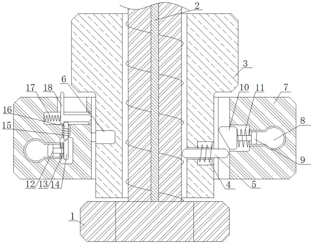
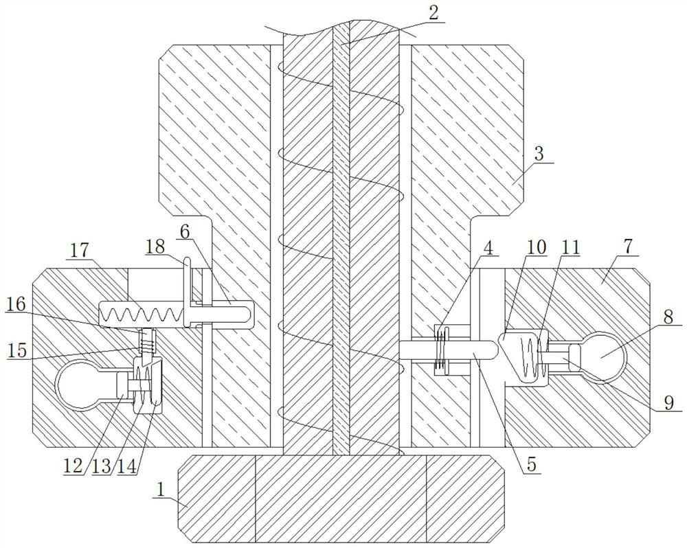
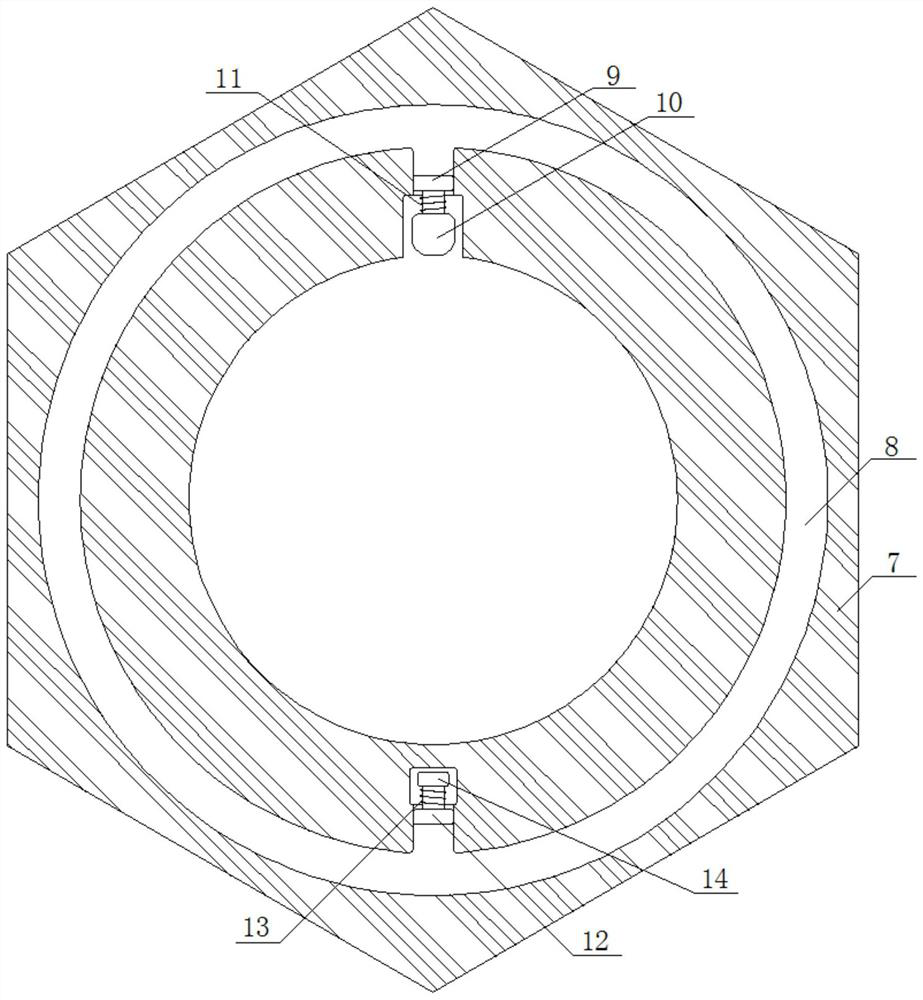
[0018] see Figure 1-5 , a bolt and nut for a train track that utilizes the principle of a connector to realize self-locking, including a bolt 1, a slot 2, an inner nut 3, a spring 4, a block 5, a self-locking slot 6, an outer nut 7, and a crooked ring Groove 8, piston rod one 9, top block 10, spring two 11, piston rod two 12, spring three 13, inclined block 14, spring four 15, limit block 16, spring five 17 and self-locking block 18, bolt 1 There is a card s...
PUM
Abstract
A bolt and nut for a train track that utilizes the principle of a connector to realize self-locking, including a bolt, a slot, an inner nut, a spring, a block, a self-locking slot, an outer nut, a crooked ring groove, a piston rod, and a top block , spring two, piston rod two, spring three, inclined block, spring four, limit block, spring five and self-locking block. The bolts and nuts used for the self-locking train track using the principle of the connector, through the cooperation of the top block and the self-locking block, the inner nut and the bolt are relatively fixed, so as to achieve the effect of self-locking. Due to the principle of the connector, the self-locking The block moves to the right under the action of spring five, and finally the self-locking block is plugged into the self-locking groove, so that the outer nut and the inner nut are relatively fixed, so as to achieve a relatively fixed effect, making the connection between the inner nut and the bolt more stable and not easy to loose , so that the self-locking effect is more stable, the train operation is safer and more secure, and the workload of maintenance personnel is reduced.
Description
technical field [0001] The invention relates to the technical field of nuts, in particular to a combination of bolts and nuts for train tracks that utilize the principle of a connector to realize self-locking. Background technique [0002] When the train is running on the track, the track will vibrate violently. Since the existing nuts and bolts cannot be self-locked, the vibration generated may cause the nuts to loosen. In severe cases, the nuts and bolts may be separated, eventually causing the train to derail. Cause serious accident, so we have proposed a kind of bolt and nut that utilizes the principle of connecting device to realize self-locking train track to solve above problem. Contents of the invention [0003] The present invention adopts the following technical solutions for realizing the technical purpose: a bolt and nut for a self-locking train track utilizing the principle of a connector, including a bolt, a slot, an inner nut, a spring, a block, a self-locki...
Claims
Application Information
Patent Timeline
Application Date:The date an application was filed.
Publication Date:The date a patent or application was officially published.
First Publication Date:The earliest publication date of a patent with the same application number.
Issue Date:Publication date of the patent grant document.
PCT Entry Date:The Entry date of PCT National Phase.
Estimated Expiry Date:The statutory expiry date of a patent right according to the Patent Law, and it is the longest term of protection that the patent right can achieve without the termination of the patent right due to other reasons(Term extension factor has been taken into account ).
Invalid Date:Actual expiry date is based on effective date or publication date of legal transaction data of invalid patent.