
Natural ventilation in the upper part of the building

A natural ventilation and building technology, applied in ventilation systems, space heating and ventilation, space heating and ventilation details, etc., can solve problems such as increasing operating costs, air introduction, rainwater exclusion, etc. Good exhaust, lower indoor temperature effect

Active Publication Date: 2021-07-09
张庭嘉
View PDF9 Cites 0 Cited by
  • Summary
  • Abstract
  • Description
  • Claims
  • Application Information

AI Technical Summary

Problems solved by technology

[0003] However, the fan needs to be driven by electricity, which will increase the operating cost, and if it rains, the fan device cannot effectively remove the rainwater, so in order to avoid water ingress and humidity inside the building, it should be solved and improved
[0004] Furthermore, there is a closed space between the upper roof of the building and the indoor ceiling. This closed space is difficult to introduce air flow into it, so the hot air cannot be effectively exported, resulting in the accumulation of hot air at the upper end of the building, making it difficult to achieve good cooling. We should try to improve it.

Method used


Image

  • Natural ventilation in the upper part of the building
  • Natural ventilation in the upper part of the building
  • Natural ventilation in the upper part of the building

Examples


Embodiment Construction

[0053] In order to have a further understanding and recognition of the features and characteristics of the present invention, the following preferred embodiments are listed below with accompanying drawings:

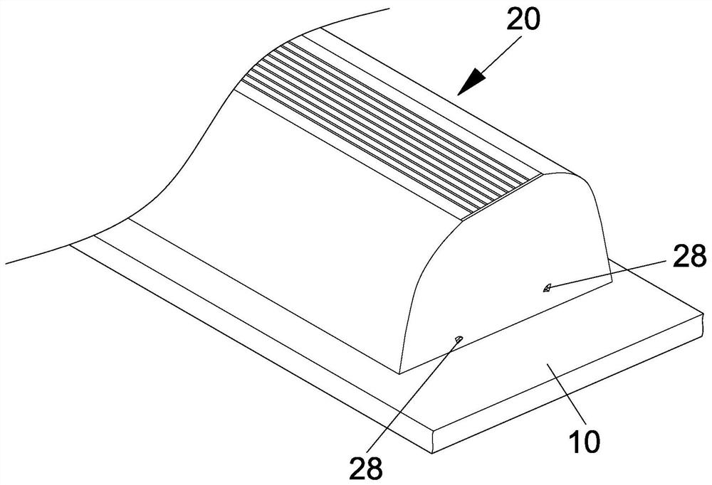
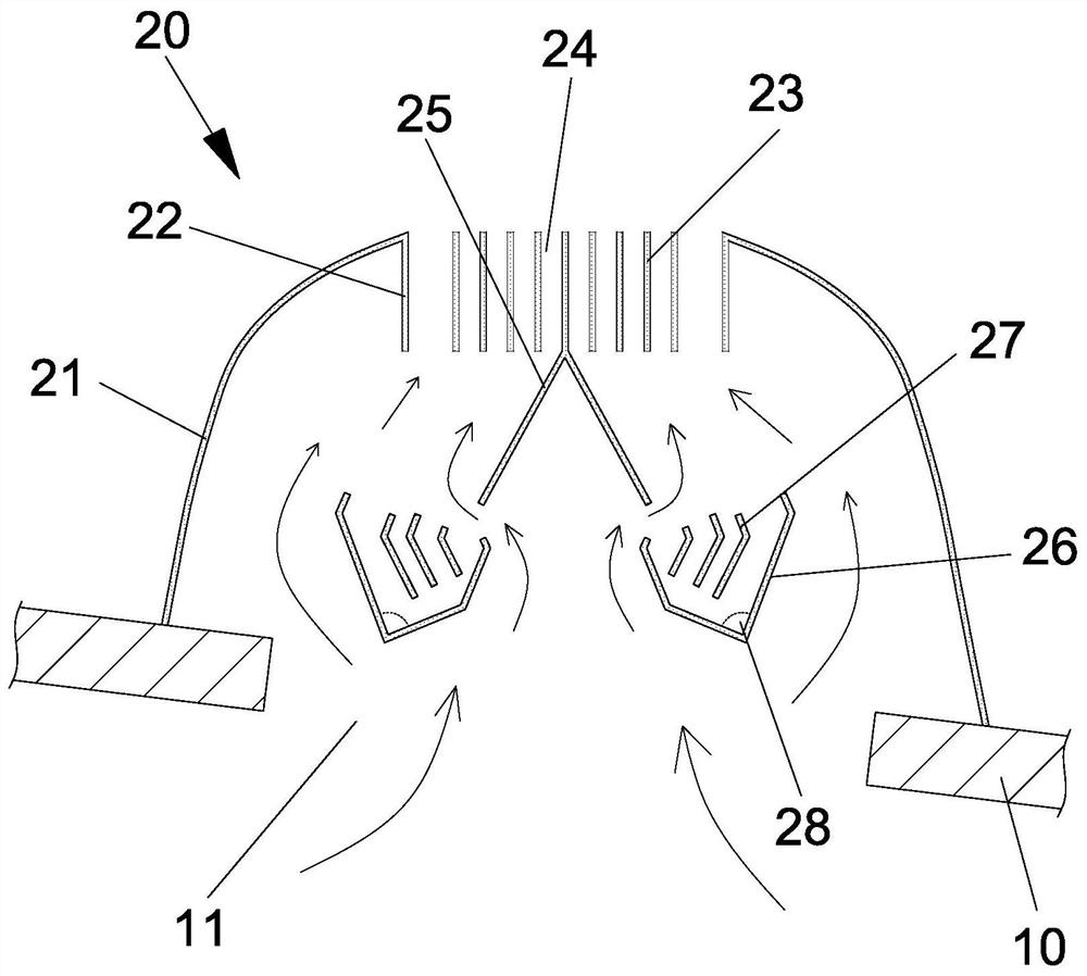
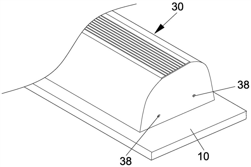
[0054] For one, see figure 1 with figure 2 , the present invention is mainly equipped with an upper slope exhaust system A20 on the roof 10 of the building, and the upper slope exhaust system A20 is installed outside the top side air outlet 11 of the roof 10, and mainly has outer covers 21 on both sides. The topmost places of the two outer covers 21 are connected with a hook back baffle 22 arranged downwards, and a plurality of rain shields 23 are arranged at the gap between the two hook back baffles 22, and the lower end of the central rain shield 23 faces to both sides. Two deflectors 25 are extended, and the lower ends of the two deflectors 25 are provided with a receiving groove 26, and a plurality of backsplash baffles 27 are arranged inside the receiving groove 26...


PUM


Abstract

The utility model relates to a natural ventilation device for the upper part of a building, which comprises an upper slope air intake and exhaust system, a side top surface exhaust system and a top plane exhaust system. The upper slope exhaust system has an outer cover body, the top of which is connected to the hook baffle, and there are rain shields, downward extending deflectors, receiving grooves and back splash baffles between the hook baffles; the side top surface exhaust The system has a cover set outside the upper side air outlet, the front end of the cover has an air outlet, and an outer baffle is installed inside the air outlet, the outer baffle is connected to the inner baffle, and the air outlets on both sides of the outer baffle are equipped with rain shields , the upper and lower ends of the upper side air outlet are equipped with inclined guide plates; the top plane exhaust system is equipped with air guide plates and rear cover body, the rear cover body is connected to the air inlet of the side top exhaust system, and the air outlet is externally connected to the guide plate. The wind plate part; removing the wind deflector part constitutes the upper slope air intake system. Each system of the present invention is equipped with a rain-shield and a water-receiving structure, which not only provide a good exhaust effect, but also effectively isolate the infiltration of external rainwater, and circulate the top air to achieve the effect of indoor cooling.

Description

technical field [0001] The present invention is a kind of natural ventilation device on the upper part of a building, more specifically, it refers to a device that can be given to the upper end of various types of buildings to achieve air circulation conversion through design. Background technique [0002] Because the interior of the iron-clad building of the factory or warehouse is relatively stuffy, which leads to a poor working environment, most operators will install intake and exhaust fans on the wall or roof of the building, so that the air in the building can circulate and achieve cooling. Effect. [0003] However, the fan needs to be driven by electricity, which will increase the cost of operation, and if it rains, the fan device cannot effectively remove the rainwater, so in order to avoid water ingress and humidity inside the building, it should be solved and improved. [0004] Furthermore, there is a closed space between the upper roof of the building and the ind...

Claims


Application Information

Patent Timeline
Patent Type & Authority Patents(China)
IPC IPC(8): F24F7/02F24F13/08
CPCF24F7/02F24F13/082F24F2007/004
Inventor 张庭嘉
Owner 张庭嘉
Learn More