Electrical test device of thyristor valve and power supply device of electrical test device

A technology of power supply device and electrical test, applied in the direction of measuring device, measuring electricity, measuring electrical variables, etc., can solve problems such as inability to meet test requirements

Active Publication Date: 2020-06-12
XIAN HIGH VOLTAGE APP RES INST CO LTD
View PDF8 Cites 0 Cited by
  • Summary
  • Abstract
  • Description
  • Claims
  • Application Information

AI Technical Summary

Problems solved by technology

When testing thyristor valves, in order to meet the requirements of testing different thyristor valves with different test parameters, the power supply device in the electrica

Method used


Image

  • Electrical test device of thyristor valve and power supply device of electrical test device
  • Electrical test device of thyristor valve and power supply device of electrical test device
  • Electrical test device of thyristor valve and power supply device of electrical test device

Examples


Embodiment 1

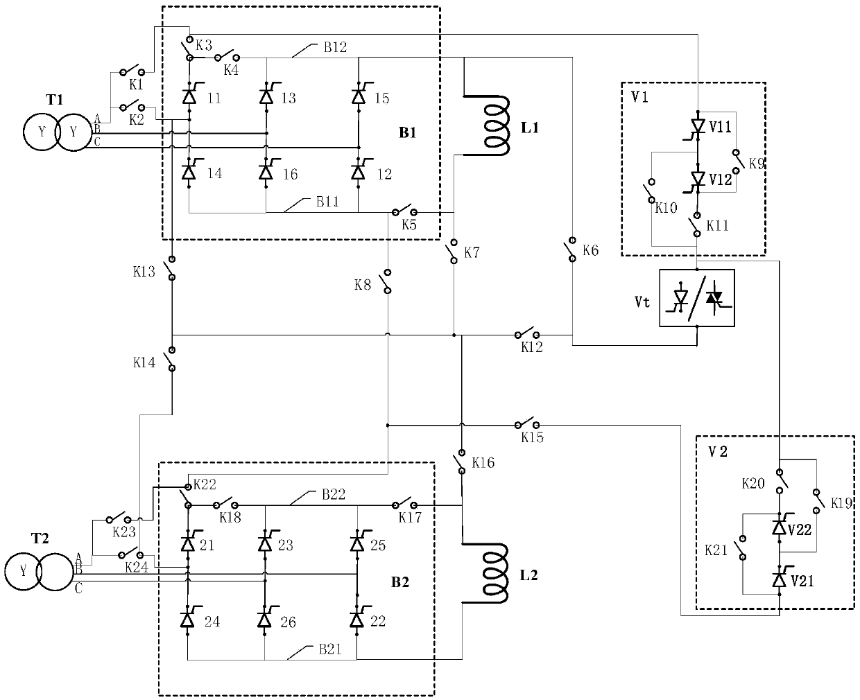
[0033] figure 1 It is a circuit diagram of a power supply device in the embodiment of the present application.

[0034] Such as figure 1 As shown, the power supply device provided by this embodiment is applied to the electrical test device for detecting the thyristor valve Vt to be detected, and the power supply device includes a first converter transformer T1, a second converter transformer T2, a first smoothing reactor L1, Second smoothing reactor L2, first 6-pulse rectifier bridge B1, second 6-pulse rectifier bridge B2, first isolation valve V1, second isolation valve V2, first switch K1, second switch K2, third switch K3 , the fourth switch K4, the fifth switch K5, the sixth switch K6, the seventh switch K7, the eighth switch K8, the twelfth switch K112, the thirteenth switch K13, the fourteenth switch K14, the fifteenth switch K15, The sixteenth switch K16, the seventeenth switch K17, the eighteenth switch K18, the twenty-second switch K22, the twenty-third switch K23, ...

Embodiment 2

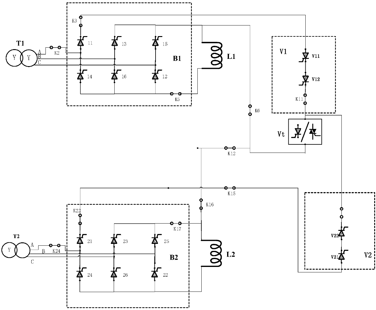
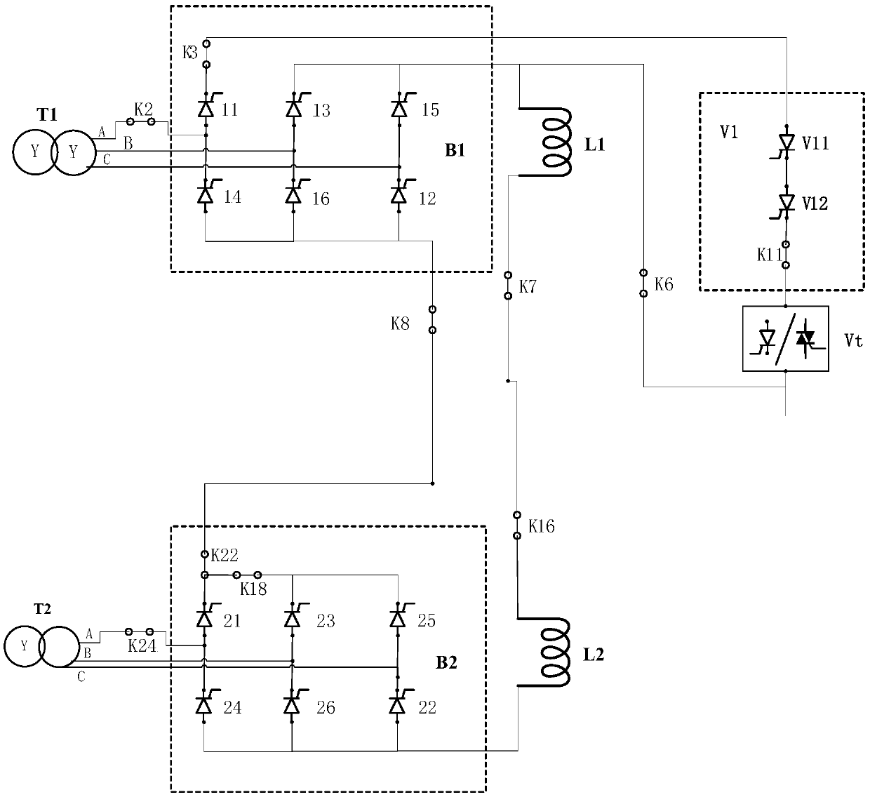
[0064] This embodiment also provides an electrical test device for a thyristor valve, the electrical test device is provided with the power supply device provided in the previous embodiment.

[0065] The power supply device specifically includes a first converter transformer, a second converter transformer, a first smoothing reactor, a second smoothing reactor, a first 6-pulse rectifier bridge, a second 6-pulse rectifier bridge, a first isolation valve, Second isolation valve, first switch, second switch, third switch, fourth switch, fifth switch, sixth switch, seventh switch, eighth switch, twelfth switch, thirteenth switch, fourteenth switch switch, fifteenth switch, sixteenth switch, seventeenth switch, eighteenth switch, twenty-second switch, twenty-third switch, and twenty-fourth switch. When a 6-pulse output request or a 12-pulse output request is received, the corresponding switch is controlled to be closed, and the connection mode of the secondary coil of the second co...


PUM


Abstract

The invention discloses an electrical test device of a thyristor valve and a power supply device of the electrical test device. The power supply device specifically comprises a first converter transformer, a second converter transformer, a first smoothing reactor, a second smoothing reactor, a first 6-pulse rectifier bridge, a second 6-pulse rectifier bridge, a first isolating valve, a second isolating valve, a first switch, a second switch, a third switch, a fourth switch, a fifth switch, a sixth switch, a seventh switch, an eighth switch, a twelfth switch, a thirteenth switch, a fourteenth switch, a fifteenth switch, a sixteenth switch, a seventeenth switch, an eighteenth switch, a twenty-second switch, a twenty-third switch and a twenty-fourth switch. When a 6-pulse output request or a12-pulse output request is received, the corresponding switch is controlled to be closed, and the connection mode of the secondary coil of the second converter transformer is controlled, so that the purpose of testing the thyristor valve to be detected in a 6-pulse rectification mode or a 12-pulse rectification mode can be achieved.

Description

technical field [0001] The present application relates to the technical field of power electronics, and more specifically, relates to an electrical test device for a thyristor valve and a power supply device thereof. Background technique [0002] With the construction of high-voltage direct current transmission projects and the maturity of high-voltage static var compensation technology, various types of thyristor valves have been used more and more widely. The performance of thyristor valves will directly affect the safety of high-voltage direct current transmission systems and high-voltage AC transmission systems. and reliability. Therefore, it is necessary to evaluate the performance of the thyristor valves used in the above-mentioned systems. Among them, how to build a suitable detection circuit for various types of thyristor valves for electrical tests is a hot issue in the current experimental technology research. [0003] The operation test is an important test item ...

Claims


Application Information

Patent Timeline
IPC IPC(8): G01R31/00
CPCG01R31/003
Inventor 张腾徐子萌王奔同聪维黄熹东张长春其他发明人请求不公开姓名
Owner XIAN HIGH VOLTAGE APP RES INST CO LTD
Why Eureka
Try Eureka