Automatic bypass cable conveying system

A bypass cable and automatic conveying technology, applied in the direction of overhead lines/cable equipment, cable suspension devices, etc., can solve the problems of high operation difficulty, high cost, and complicated laying methods, and achieve simple structural design, low cost, and easy operation convenient effect

Pending Publication Date: 2020-06-12
GUANGDONG POWER GRID CO LTD +1
View PDF0 Cites 4 Cited by
  • Summary
  • Abstract
  • Description
  • Claims
  • Application Information

AI Technical Summary

Problems solved by technology

However, this laying method is complicated and requires additional support, which is difficult to operate and expensive

Method used


Image

  • Automatic bypass cable conveying system
  • Automatic bypass cable conveying system
  • Automatic bypass cable conveying system

Examples


Embodiment Construction

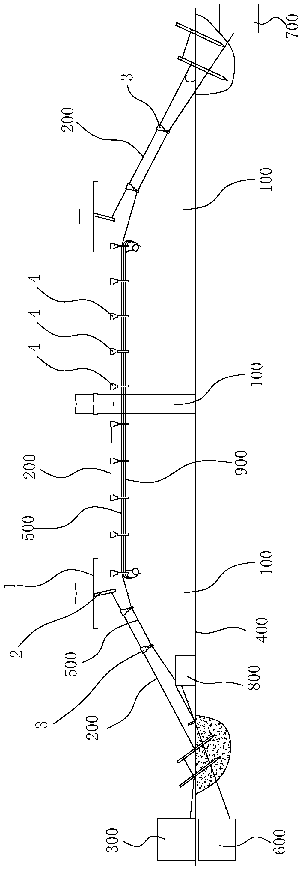
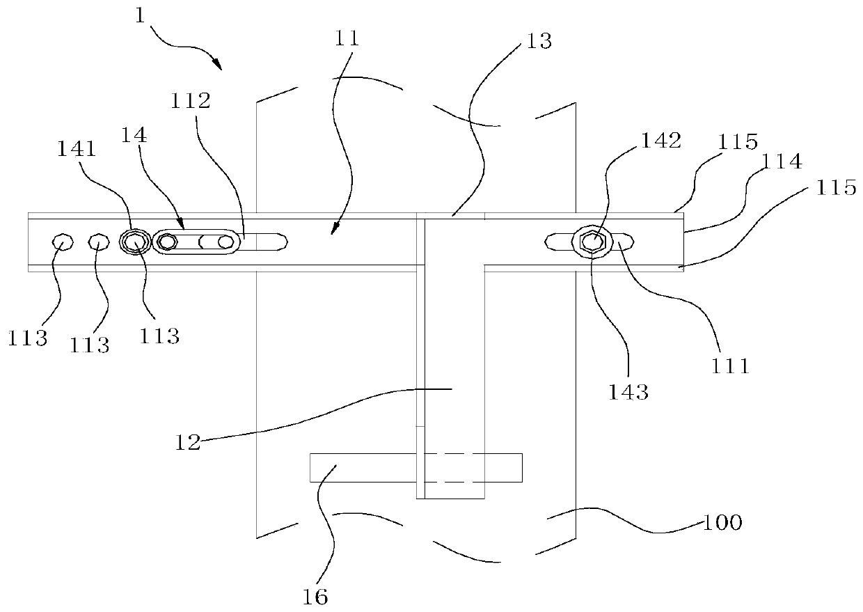
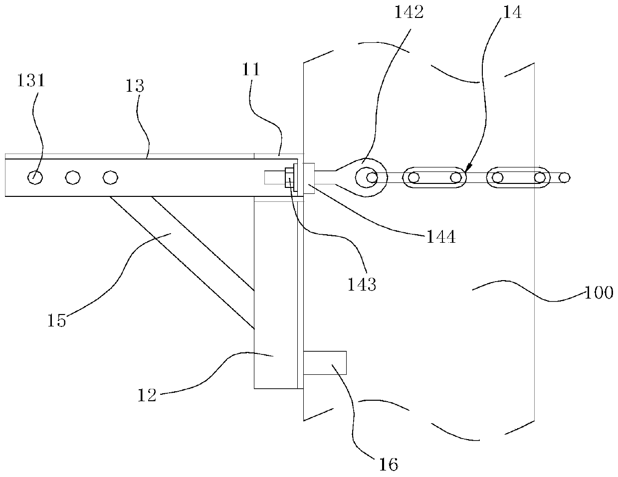
[0040] like figure 1 As shown, the bypass cable automatic conveying system of the embodiment of the present invention includes a pole 100, a track 200, a traction assembly 3 and a cable assembly 4, wherein the pole 100 is an existing pole 100 in the current grid system environment, The pole 100 is provided with a support assembly 1, the support assembly 1 is connected with a suspension assembly 2, the track 200 is arranged as a rope structure, and one end of the track 200 is wound on the first pay-off frame 300, The other end passes through the suspension assembly 2 in turn and is fixed on the ground 400, the track 200 is in a tight state; there are multiple traction assemblies 3, and multiple traction assemblies 3 are slidably arranged on the track 200 Above, all the traction components 3 are connected by a traction rope 500, one end of the traction rope 500 is wound on the second pay-off frame 600, and the other end passes through all the traction components 3 and is connect...


PUM


Abstract

The invention relates to an automatic bypass cable conveying system. The system comprises an electric pole, a track, a traction assembly and a cable supporting assembly. A supporting assembly is arranged on the electric pole. The supporting assembly is connected with a hanging assembly. The rail is arranged to be of a rope structure. The hanging rod is arranged on the hanging assembly after beingtightened. Two ends of the track are respectively connected with the first pay-off rack and the ground. The plurality of traction assemblies are connected with the traction rope and are arranged on the rail in a sliding manner. Two ends of the traction rope are respectively connected with the second pay-off rack and the lead rack. A traction machine capable of pulling the traction rope to move isfurther arranged on one side of the second pay-off rack. The cable supporting assemblies are connected with the traction rope and arranged on the rail in a sliding mode, each cable supporting assemblyis provided with a first fixing position for fixing the traction rope and a second fixing position for supporting the bypass cable, and the bypass cable is not pulled in the conveying process. The automatic bypass cable conveying system is simple in structure and convenient to convey.

Description

technical field [0001] The invention relates to the technical field of power grid maintenance equipment, in particular to an automatic delivery system for bypass cables. Background technique [0002] With the continuous increase of residents' electricity consumption, entering the autumn and winter seasons, the residents' electricity consumption increases. Once the power is cut off for maintenance, it will inevitably affect the residents' production and living electricity consumption. At present, more and more live bypass operations are used in daily maintenance work. Among them, for sudden power failures, it is necessary to carry out maintenance when the power cables are completely cut off, the time to restore power supply is difficult to control, and the losses caused cannot be estimated. In this context, the 10kV bypass live working method is widely used , this method can build a temporary power supply system in a short time under the state of uninterrupted power supply, t...

Claims


Application Information

Patent Timeline
Patent Type & Authority Applications(China)
IPC IPC(8): H02G1/04H02G7/05
CPCH02G1/04H02G7/05
Inventor 舒坚邱灿树陈永平余克光梁小强丁瑞蓉刘植辉黄奕龙林新宇
Owner GUANGDONG POWER GRID CO LTD
Why Eureka
Try Eureka