Linear motor structure

A linear motor and friction part technology, applied in the field of linear motor structure, can solve the problems of inability to make full use of the magnetic force of magnetic steel, complexity, etc.

Active Publication Date: 2021-06-29
GREE ELECTRIC APPLIANCES INC
View PDF0 Cites 0 Cited by
  • Summary
  • Abstract
  • Description
  • Claims
  • Application Information

AI Technical Summary

Problems solved by technology

[0005] The main purpose of the present invention is to provide a linear motor structure to solve the complicated problem that the braking system of the linear motor in the prior art cannot fully utilize the magnetic force of the magnet steel

Method used


Image

  • Linear motor structure
  • Linear motor structure
  • Linear motor structure

Examples


Embodiment Construction

[0033] It should be noted that, in the case of no conflict, the embodiments in the present application and the features in the embodiments can be combined with each other. The present invention will be described in detail below with reference to the accompanying drawings and examples.

[0034] It should be pointed out that the following detailed description is exemplary and intended to provide further explanation to the present application. Unless defined otherwise, all technical and scientific terms used herein have the same meaning as commonly understood by one of ordinary skill in the art to which this application belongs.

[0035] It should be noted that the terminology used here is only for describing specific implementations, and is not intended to limit the exemplary implementations according to the present application. As used herein, unless the context clearly dictates otherwise, the singular is intended to include the plural, and it should also be understood that wh...


PUM


Abstract

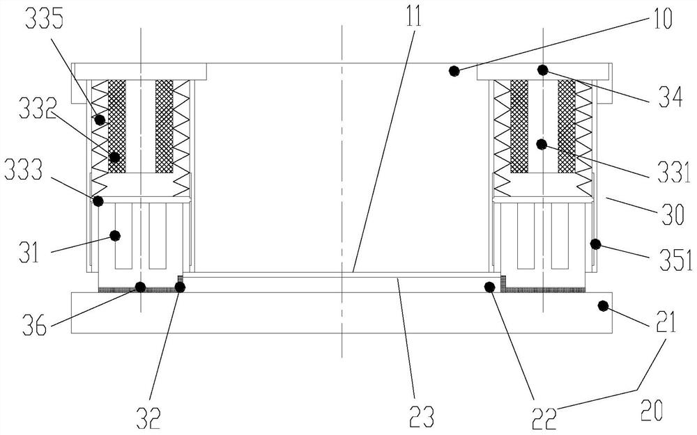
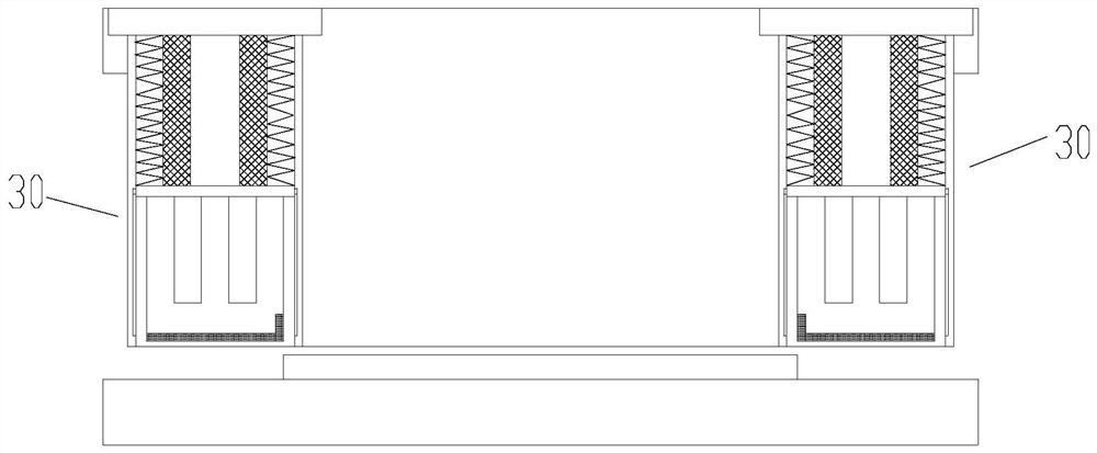
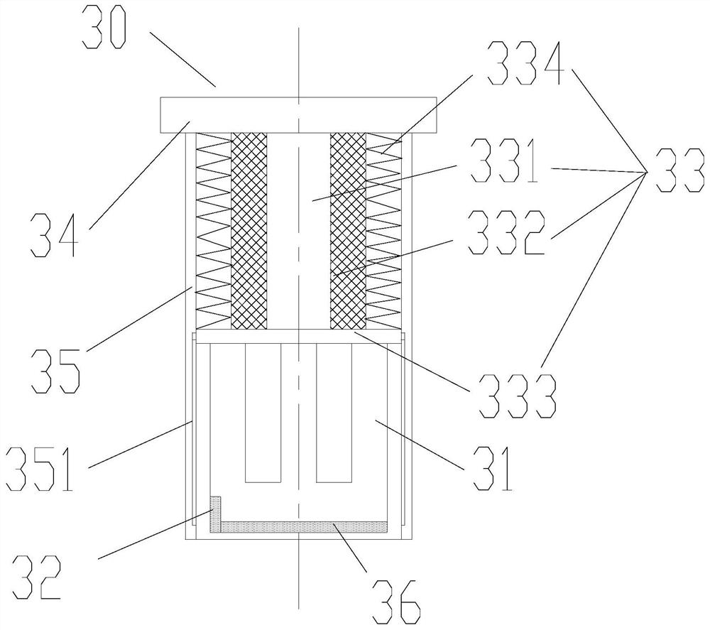
The invention provides a linear motor structure, comprising: a linear motor body, including a mover and a stator, the mover has a mover end face; the stator includes a stator mounting plate and a magnetic steel, the magnetic steel is arranged on the stator mounting plate, and the magnetic steel has The side surface of the magnet steel and the end surface of the magnet steel, the end surface of the magnet steel and the end surface of the mover are arranged opposite to each other along the first preset direction; the brake assembly, the brake assembly is arranged on the mover, the brake assembly includes a moving part and a first friction part, the second A friction part has a first separation position separated from the magnetic steel and a first braking position adsorbed on the side of the magnetic steel. The first friction part is arranged on the moving part; the moving part is movably arranged to drive the first friction part Moves between a first detent position and a first disengaged position. The linear motor structure of the present invention solves the complicated problem that the braking system of the linear motor in the prior art cannot make full use of the magnetic force of the magnet steel.

Description

technical field [0001] The invention relates to the field of braking devices, in particular to a linear motor structure. Background technique [0002] For the traditional transmission mode of rotating motor plus screw, since the motor and the working parts have to go through intermediate links such as gears, screw pairs, couplings, etc., there are elastic deformation, backlash, motion hysteresis, friction, vibration, etc. , noise and wear and other problems, and the above problems are difficult to fundamentally solve. Moreover, the operating speed of the above-mentioned transmission mode is relatively low, generally only reaching 30-40 m / min. The linear servo transmission system adopts the direct drive method, which has the advantages of wide operating speed range, high acceleration and high positioning accuracy. The speed can exceed 200m / min, and the acceleration can reach more than 10g. It is especially suitable for precision and high-speed applications, such as high-end ...

Claims


Application Information

Patent Timeline
Patent Type & Authority Patents(China)
IPC IPC(8): H02K41/02H02K7/102H02K1/17
CPCH02K1/17H02K7/102H02K41/02
Inventor 马云凌谢芳郜曦郑立章刘吉胜张海斌
Owner GREE ELECTRIC APPLIANCES INC
Why Eureka
Try Eureka