Radio frequency front-end circuit and electronic equipment

A radio frequency front-end and circuit technology, which is applied in the field of communication, can solve problems such as large radio frequency signal interference, poor antenna isolation, and poor path loss control, and achieve the effects of reducing interference, improving component loss, and reducing path loss

Inactive Publication Date: 2020-06-12
VIVO MOBILE COMM CO LTD
View PDF6 Cites 8 Cited by
  • Summary
  • Abstract
  • Description
  • Claims
  • Application Information

AI Technical Summary

Problems solved by technology

[0004] The purpose of the embodiment of the present application is to provide a radio frequency front-end circuit and electronic equipment to solve the problems

Method used


Image

  • Radio frequency front-end circuit and electronic equipment
  • Radio frequency front-end circuit and electronic equipment
  • Radio frequency front-end circuit and electronic equipment

Examples


Embodiment 1

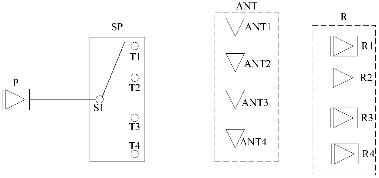
[0034] An embodiment of the present application provides a radio frequency front-end circuit. The radio frequency front-end circuit may be a radio frequency front-end circuit used in an electronic device to connect to a wireless communication network. The wireless communication network may be a 2G wireless communication network, a 3G wireless communication network, a 4G A wireless communication network or a 5G wireless communication network, or a higher-level wireless communication network, etc. The radio frequency front-end circuit may include a signal transmission path and a signal reception path, wherein the number of the signal transmission path and the signal reception path may be set according to actual conditions, that is, the radio frequency front-end circuit may include one or more signal transmission paths, and One or more signal receiving paths, the signal transmitting path may include the transmitting module P and the antenna ANT, and the signal receiving path may i...

Embodiment 2

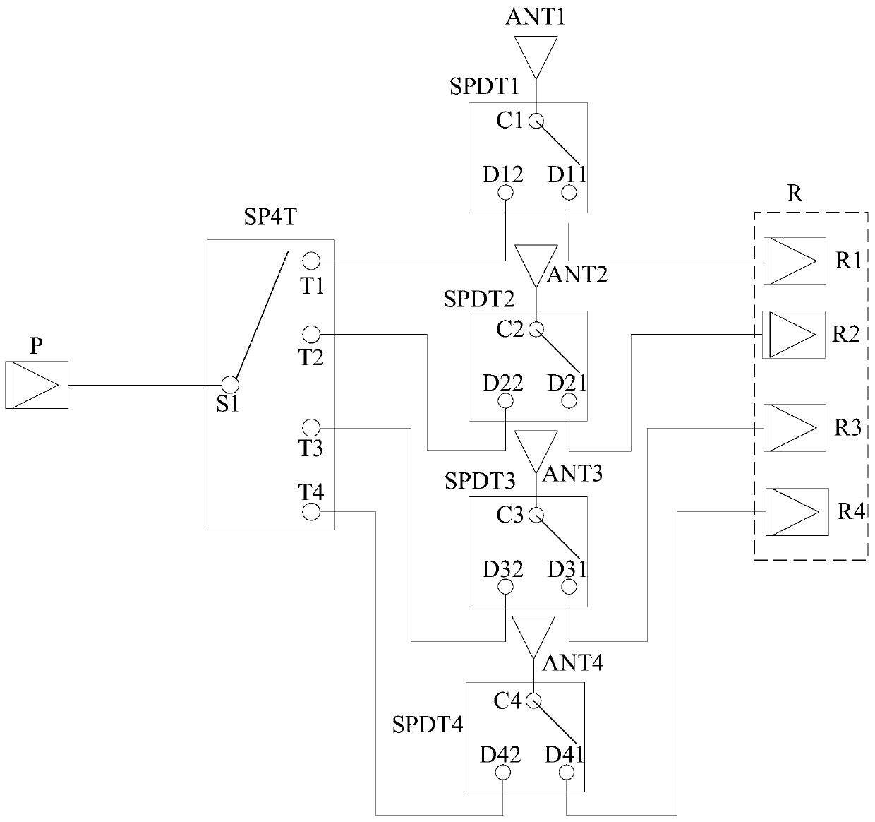
[0050] image 3 Another radio frequency front-end circuit provided for the embodiment of the present application, the radio frequency front-end circuit includes Figure 1 ~ Figure 2 All the functional units of the RF front-end circuit shown, and on the basis of it, it has been improved, and the improvements are as follows:

[0051] In order to better control each path (including signal transmission path and signal reception path) formed by connecting the antenna ANT, a single-pole double-throw switch SPDT can be set to realize one or more signal transmission paths and multiple signal reception paths. Specifically, a plurality of single-pole double-throw switches SPDT may be provided according to actual conditions, and the single-pole double-throw switch SPDT may include one input terminal and two output terminals. The input end can be connected with any output end, and one output end of each single-pole double-throw switch SPDT is connected with an output end of the single-po...

Embodiment 3

[0081] The above is the radio frequency front-end circuit provided by the embodiment of the present application. Based on the same idea, the embodiment of the present application further provides an electronic device, and the electronic device includes the radio frequency front-end circuit.

[0082] The RF front-end circuit includes a transmitting module P, a single-pole multi-throw switch SP, multiple receiving modules R and multiple antennas ANT, wherein:

[0083] The transmitting module P is connected to the input end of the single-pole multi-throw switch SP, and the multiple output ends of the single-pole multi-throw switch SP are respectively connected to the multiple antennas ANT in a one-to-one correspondence manner;

[0084] The multiple receiving modules R are respectively connected to the multiple antennas ANT in a one-to-one correspondence manner.

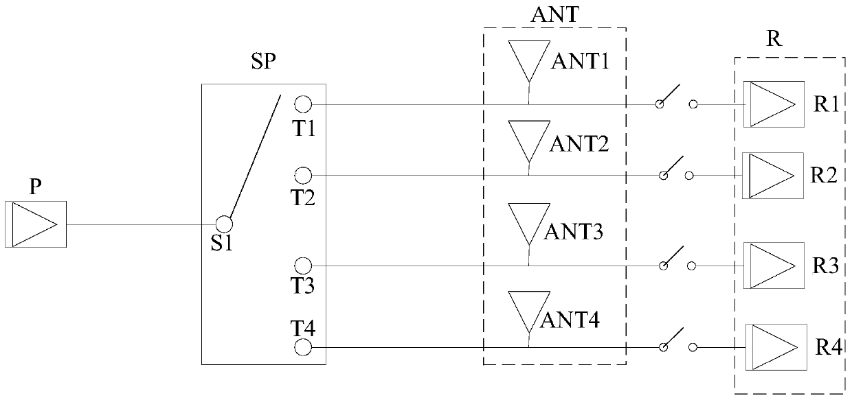
[0085] In the embodiment of the present application, the radio frequency front-end circuit further includes a plurality ...


PUM


Abstract

The embodiment of the invention discloses a radio frequency front-end circuit and electronic equipment. The radio frequency front-end circuit comprises a transmitting module, a single-pole multi-throwswitch, a plurality of receiving modules and a plurality of antennas, the transmitting module is connected with the input end of the single-pole multi-throw switch, and a plurality of output ends ofthe single-pole multi-throw switch are respectively connected with the plurality of antennas in a one-to-one correspondence mode; and the plurality of receiving modules are respectively connected withthe plurality of antennas in a one-to-one correspondence manner. Method, based on one single-pole multi-throw switch, one or more signal transmitting paths in a communication network can be realized.According to the utility model, functions of a plurality of signal transmitting paths and a plurality of signal receiving paths are realized, and through the signal transmitting paths and the signalreceiving paths formed by the above structure, element difference loss caused by different elements can be improved, flexibility of circuit layout is increased, interference among radio frequency signals can be reduced, and path loss can be reduced.

Description

technical field [0001] The present application relates to the technical field of communications, and in particular to a radio frequency front-end circuit and electronic equipment. Background technique [0002] With the popularization of mobile smart terminals, users' demand for data traffic continues to increase. For example, the peak rate of 5G NR can reach 20Gbps. The increase in rate requires 5G NR to have the capability of 4*4MIMO. The operating frequency required for electronic equipment is getting higher and higher, and the bandwidth is getting bigger and bigger, which challenges the limits of components. [0003] Generally, the functions of one transmit channel and four receive channels in the radio frequency front-end circuit can be realized by multiple three-pole three-throw switches. However, in the above method, the layout and routing of electronic devices will directly affect the path loss, and the three-pole three-throw switch will make the isolation between an...

Claims


Application Information

Patent Timeline
IPC IPC(8): H04B1/40
CPCH04B1/40
Inventor 盛雪锋
Owner VIVO MOBILE COMM CO LTD
Why Eureka
Try Eureka