Electromagnetic device and method for orderly deposition of wear particles

A technology of wear particles and electromagnetic devices, applied in particle and sedimentation analysis, measuring devices, chemical instruments and methods, etc., can solve the problems of inability to achieve orderly deposition of wear particles, increase the volume and complexity of the device, and avoid deposition Regular destruction, avoiding temperature rise, and prolonging the service life

Active Publication Date: 2020-06-16
SHANDONG UNIV
View PDF13 Cites 1 Cited by
  • Summary
  • Abstract
  • Description
  • Claims
  • Application Information

AI Technical Summary

Problems solved by technology

However, the deposition device cannot realize the orderly deposition of wear particles, and the mixed use of permanent magnets and electromagnets increases the volume and complexity of the device
[0005] Therefore, the inventors found that in the deposition devices of online ferrography at the present stage, there is no device structure that can effectively realize the orderly deposition of wear particles and obtain the size distribution characteristics of wear particles

Method used


Image

  • Electromagnetic device and method for orderly deposition of wear particles
  • Electromagnetic device and method for orderly deposition of wear particles
  • Electromagnetic device and method for orderly deposition of wear particles

Examples


Embodiment 1

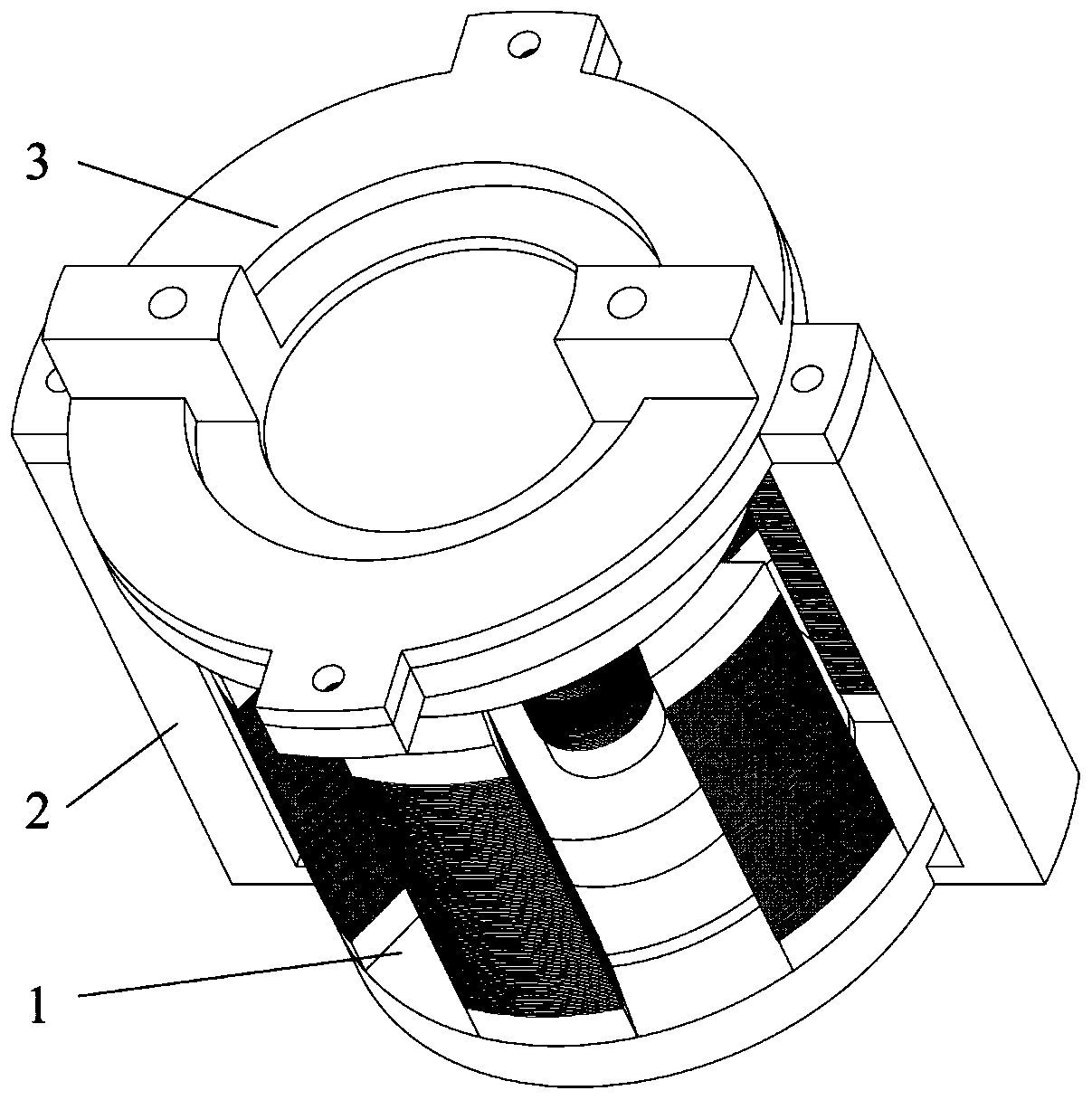
[0035] Embodiment 1 of the present disclosure discloses an electromagnetic device for orderly deposition of wear particles, which mainly includes:

[0036] Inner electromagnet—at least two sets of enamelled copper wires are wound on the inner electromagnet column, and the magnetic induction intensity is controlled by controlling the on and off of the current in the coil. There is a through hole in the center of the magnet for the placement of the flow channel;

[0037] Outer electromagnet—the outer electromagnet includes at least two sets of columns and the number of sets is the same as that of the inner electromagnet copper wires. The columns are wound with enamelled copper wires, and the magnetic induction intensity is controlled by controlling the on-off of the current in each set of coils;

[0038] Yoke—connects the magnetic circuit and transmits the magnetic field lines.

[0039] Flow Passages - The lubricating oil flows through the deposit areas through flow passages.

...

Embodiment 2

[0051] Embodiments of the present disclosure also disclose a deposition method of an electromagnetic device for orderly deposition of wear particles, which mainly includes the following steps:

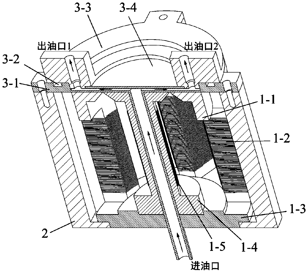
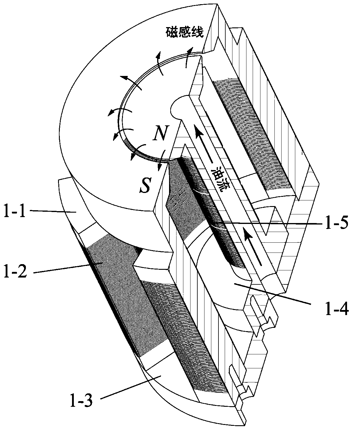
[0052] The intensity of the annular deposition magnetic field generated by the electromagnet 1 is adjusted by controlling the number of energized coils. When the device is in operation, firstly, the columns opposite to the outer electromagnet form a group, and the same current of a certain intensity is passed to a group of outer electromagnet coils and a group of inner electromagnet coils, and a group of outer electromagnet coils 1-2 and a group of The inner electromagnet coil 1-3 is fed with the same current of a certain intensity, and the electromagnet 1 will generate a high-gradient magnetic field of a certain intensity between the lower part 3-1 of the flow channel and the upper part 3-3 of the flow channel, and the magnetic field will make the Ferromagnetic particles with a size o...


PUM

PropertyMeasurementUnit
sizeaaaaaaaaaa

Abstract

The invention relates to an electromagnetic device for orderly deposition of wear particles, and belongs to the technical field of lubricating oil monitoring devices. The device comprises an inner magnet, an outer magnet, a flow channel and a magnet yoke, wherein a through hole is formed in the center of the inner magnet; multiple groups of coils are wound on the outer surface of the inner magnet;the outer magnet is composed of multiple sections of stand columns and circumferentially distributed around the inner magnet with the inner magnet as the center; each stand column is wound with the coils in the same direction; the coil winding direction of the outer magnet is opposite to that of the inner magnet; the magnet yoke is used for fixing the inner magnet and the outer magnet; a center hole is formed in the center of the magnet yoke; the flow channel comprises an upper flow channel and a lower flow channel; an oil outlet hole is formed in the upper flow channel; the lower flow channel comprises an oil inlet pipe and a surface deposition area; the oil inlet pipe is arranged in the through hole in the center of the inner magnet; and the flow channel and the magnet yoke are fixedlyconnected with the inner and outer magnets through buckles. According to the device, the magnetic induction intensity is adjusted by changing the group number of the electrified coils, and orderly separation of the wear particles in a deposition area according to the size in the online monitoring process is achieved.

Description

technical field [0001] The disclosure belongs to the technical field of lubricating oil monitoring devices, in particular to an electromagnetic device and method for orderly deposition of wear particles. Background technique [0002] The statements herein merely provide background information related to the present disclosure and do not necessarily constitute prior art. [0003] Ferrography is a method of separating ferromagnetic wear particles from the lubrication system of mechanical equipment by using a high-gradient strong magnetic field, and then observing and analyzing them. Off-line ferrography (including direct-reading, analytical, and rotary) uses a permanent magnet with a specific structure to achieve orderly deposition of wear particles. The size, concentration, material and morphology information of wear particles can be obtained by densitometer, ferrographic microscope and scanning electron microscope. However, offline analysis is inseparable from manual sampl...

Claims


Application Information

Patent Timeline
Patent Type & Authority Applications(China)
IPC IPC(8): B03C1/025B03C1/033B03C1/031G01N15/02
CPCB03C1/025B03C1/0335B03C1/031G01N15/0266
Inventor 王黎明孙佳毅李方义李剑峰李建勇
Owner SHANDONG UNIV
Why Eureka
Try Eureka