
Coating and curing production line

A coating and production line technology, applied in the direction of coating, device for coating liquid on surface, surface pretreatment, etc., can solve problems such as operator's health injury, equipment injury, inability to complete, etc., to achieve modernization of production, The effect of reducing the volatilization of the coating liquid and improving the production efficiency

Active Publication Date: 2020-06-16
SUZHOU MICROBIT AUTOMATION CO LTD
View PDF11 Cites 8 Cited by
  • Summary
  • Abstract
  • Description
  • Claims
  • Application Information

AI Technical Summary

Problems solved by technology

[0004] Tempo requirements: the first coating, the first drying, the first curing, the second coating, the second drying, the second curing, the timing of the whole process needs to be strictly controlled, but each step The required time varies, so the composition of the entire production line should not only consider the individuality of each step, but also consider the continuity of the entire production line's production actions. In addition, considering the different rhythms of each product, it must be able to adjust in real time beat parameters, while the existing coating and curing production line cannot be completed
[0005] At the same time, the existing coating and curing production line has limited space for placing the curing box, and the curing light source cannot be turned off during the production process.
Since the curing light is strong and harmful to the human body, no light leakage is allowed. However, the curing box on the market adopts a single-door light-blocking method. When the vehicle is put into or taken out of the curing box, the door needs to be opened, which will cause light to leak out and take a long time. Time will not only cause damage to the equipment, but also to the health of the operator

Method used


Image

  • Coating and curing production line
  • Coating and curing production line
  • Coating and curing production line

Examples


Embodiment

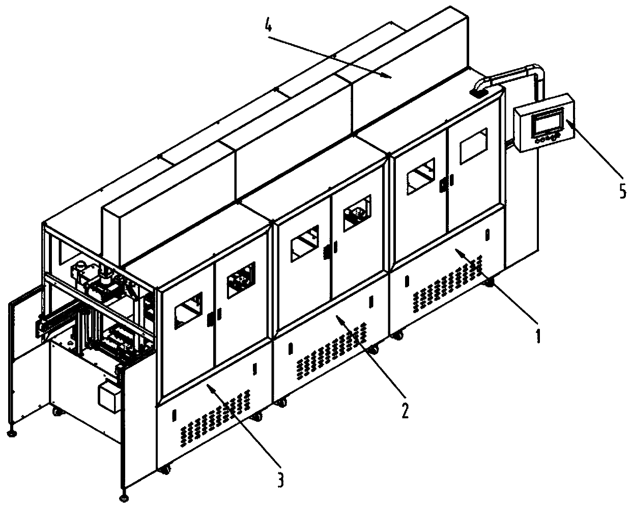
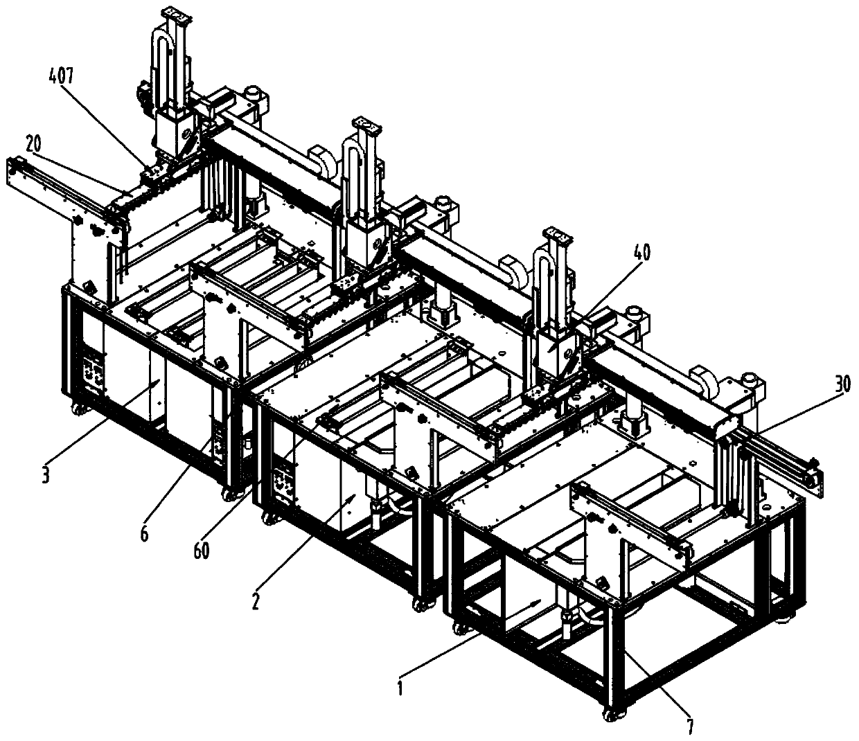
[0092] see Figure 2-23 , figure 2 It is a structural schematic diagram of the complete machine of this embodiment; image 3 It is a schematic diagram of the internal structure of the complete machine of this embodiment; Figure 4 It is a schematic structural diagram of the vehicle in this embodiment; Figure 5 It is a schematic diagram of the internal structure of the vehicle in this embodiment; Image 6 It is a schematic diagram of the structure of the cover plate of the carrier in this embodiment; Figure 7 It is a structural schematic diagram of the vehicle looking up in this embodiment; Figure 8 for Figure 7 The enlarged schematic diagram of part I in the middle; Figure 9 It is a structural schematic diagram of the first part of the whole machine in this embodiment; Figure 10 It is a schematic structural diagram of the second part of the whole machine in this embodiment; Figure 11 It is a schematic structural diagram of the third part of the complete machine i...


PUM


Abstract

The invention discloses a coating and curing production line. The production line comprises a carrier and a machine. The carrier comprises a carrying plate and one or more carrying shafts. The carrying shafts are installed on the carrying plate, and a to-be-processed product can be installed on the carrying shafts. The machine is provided with a first part, a second part and a third part in the forward direction of the x axis of the machine in sequence, the first part and the second part each comprise a coating device, the second part further comprises an illumination curing box, and the thirdpart comprises one or more illumination curing boxes. The first part coats the to-be-processed product for the first time, the second part performing first-time curing and second-time coating on theto-be-processed product which is coated one time in sequence, and the third part cures the to-be-processed product which is cured twice for the second time. The coating and curing production line is high in universality, production efficiency and stability, and through sectional-type design, the takt of each step can be better controlled.

Description

technical field [0001] The invention relates to the technical field of coating and curing equipment, in particular to a coating and curing production line. Background technique [0002] The existing coating and curing production lines are generally not very versatile and cannot be compatible with products of different specifications and models at the same time. The production efficiency is low and cannot meet the production requirements. At the same time, the existing coating and curing production lines do not have liquid blowing equipment function, for some products such as urinary catheters, which have drainage holes 103, such as figure 1 Shown in the figure, 101 is the excretion tapered interface, 102 is the tube body of catheter, and 103 is the excretion eyelet. Therefore, when the product is coated, the coating liquid will enter the discharge hole 103 , but the existing carrier cannot discharge the coating liquid in the discharge hole 103 more conveniently. [0003] I...

Claims


Application Information

Patent Timeline
IPC IPC(8): B05C9/12B05C3/10B05C11/10B05C11/11B05C13/02B05D3/06
CPCB05C9/12B05C3/10B05C13/02B05C11/1039B05C11/11B05D3/067
Inventor 李光辉严琴穆岩
Owner SUZHOU MICROBIT AUTOMATION CO LTD
Learn More