Radial expansion mechanism and assembly jig

A technology for assembling jigs and jigs, which is applied in the field of machinery and can solve problems such as improper assembly, displacement of parts, and difficulty in controlling tolerances.

Inactive Publication Date: 2020-06-16
LUXSHARE ELECTRONICS TECH (KUNSHAN) LTD
View PDF6 Cites 0 Cited by
  • Summary
  • Abstract
  • Description
  • Claims
  • Application Information

AI Technical Summary

Problems solved by technology

Traditional assembly and pressure-holding devices usually use one-way or opposite movement. When applied to parts with curved surfaces, it is easy to cause the parts to shift and it is difficult to control the tolerances in all directions, which can easily lead to improper assembly and failure to meet the requirements. Assembly requirements

Method used


Image

  • Radial expansion mechanism and assembly jig
  • Radial expansion mechanism and assembly jig
  • Radial expansion mechanism and assembly jig

Examples


Embodiment 1

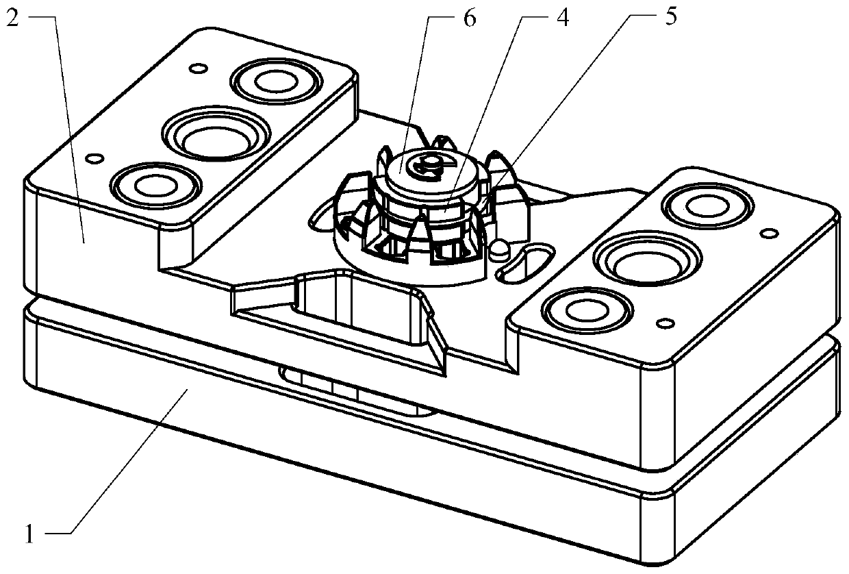
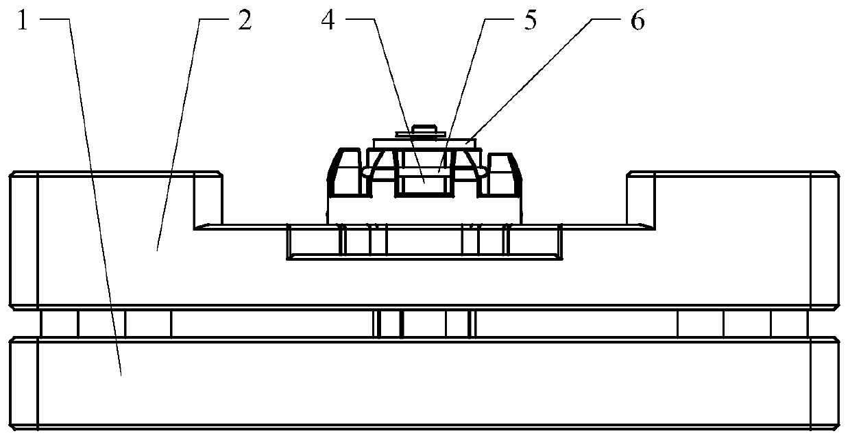
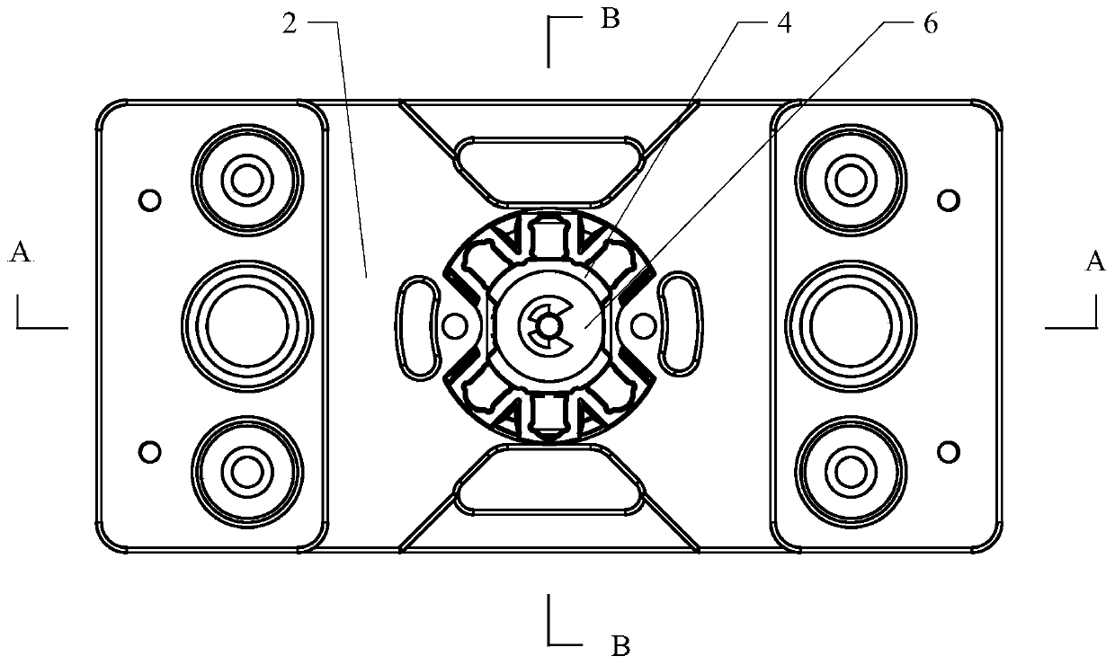
[0040] Figure 1-Figure 3 They are respectively the three-dimensional structure schematic diagram, the front view and the top view of the radial expansion mechanism of this embodiment, Figure 4 and Figure 5 respectively image 3 Schematic cross-sectional views of the radial expansion mechanism in A-A direction and B-B direction. Such as Figure 1-Figure 5 As shown, the radial expansion mechanism of this embodiment includes a base 1 , a stage 2 , a push block 3 , at least two slide blocks 4 , a reset device and a pressure plate 6 . The stage 2 is arranged above the base 1 and is movably connected with the upper end surface of the base 1 . The lower end of the push block 3 is fixedly connected to the base 1 , the push block 3 has at least one first slope 31 , and the slide block 4 is arranged outside the push block 3 . The reset device is connected with the sliding block 4 and is used to keep the sliding block 4 in contact with the first slope 31 of the push block 3 . Th...

Embodiment 2

[0053] The radial expansion mechanism in Embodiment 1 can cooperate with other components to form an assembly jig. Figure 8 is a schematic structural view of the assembly jig of this embodiment. In an alternative embodiment, such as Figure 8 As shown, the assembly jig of this embodiment includes the indenter 91 and the radial expansion mechanism in the first embodiment.

[0054] During the assembly process of the product, it is often necessary to install other workpieces on the inner side of the housing and the ring-shaped workpiece by bonding, welding or the like. This embodiment takes assembling the anti-theft buckle, that is, bonding a plurality of magnets inside the hemispherical casing 8 as an example, to describe the structure and usage of the assembling jig.

[0055] The stage 2 can be provided with profiling grooves corresponding to the shape of the magnets, a plurality of magnets are placed in the corresponding profiling grooves, and there can be a certain interva...


PUM


Abstract

The embodiment of the invention discloses a radial expansion mechanism and an assembly jig. A push block (3) is fixedly connected with a base (1) and is provided with at least one first inclined surface (31), wherein at least two sliding blocks (4) are arranged on the outer side of the push block (3); a pressing disc (6) is arranged above the sliding blocks (4) and is fixedly connected with an objective table (2); and when the objective table (2) moves, the pressing disc (6) moves along with the objective table (2) to push the sliding blocks (4) to move along the first inclined surface (31) ofthe push block (3), so that the distance between the sliding blocks (4) and the center of the push block (3) is changed, the outer contours of the sliding blocks (4) are expanded in the radial direction, and workpieces arranged on the outer sides of the sliding blocks (4) are driven to move. Therefore, according to the technical scheme of the embodiment of the invention, a plurality of radial external forces can be applied to the workpieces on the outer sides of the sliding blocks (4) at the same time, so that the products can be conveniently assembled and subjected to pressure maintaining.

Description

technical field [0001] The invention relates to the mechanical field, in particular to a radial expansion mechanism and an assembly jig. Background technique [0002] In the process of product production, it is often necessary to expand parts or assemble and hold parts with curved surfaces. Traditional assembly and pressure-holding devices usually use one-way or opposite movement. When applied to parts with curved surfaces, it is easy to cause the parts to shift and it is difficult to control the tolerances in all directions, which can easily lead to improper assembly and failure to meet the requirements. Assembly requirements. Contents of the invention [0003] In view of this, the embodiment of the present invention provides a radial expansion mechanism and an assembly jig, which can move the workpiece in the radial direction, so as to facilitate the assembly and pressure maintenance of the product. [0004] In the first aspect, the embodiment of the present invention ...

Claims


Application Information

Patent Timeline
IPC IPC(8): B21D31/04
CPCB21D31/04
Inventor 孙晓林刘栋洋景荣强周静张良
Owner LUXSHARE ELECTRONICS TECH (KUNSHAN) LTD
Why Eureka
Try Eureka