Cutting thickness adjustable tablet cutting device
A technology of cutting thickness and cutting device, applied in solid separation, sieve, grid and other directions, can solve the problems of trouble, inability to cut tablets, manual operation and so on
- Summary
- Abstract
- Description
- Claims
- Application Information
AI Technical Summary
Problems solved by technology
Method used
Image
Examples
Embodiment 1
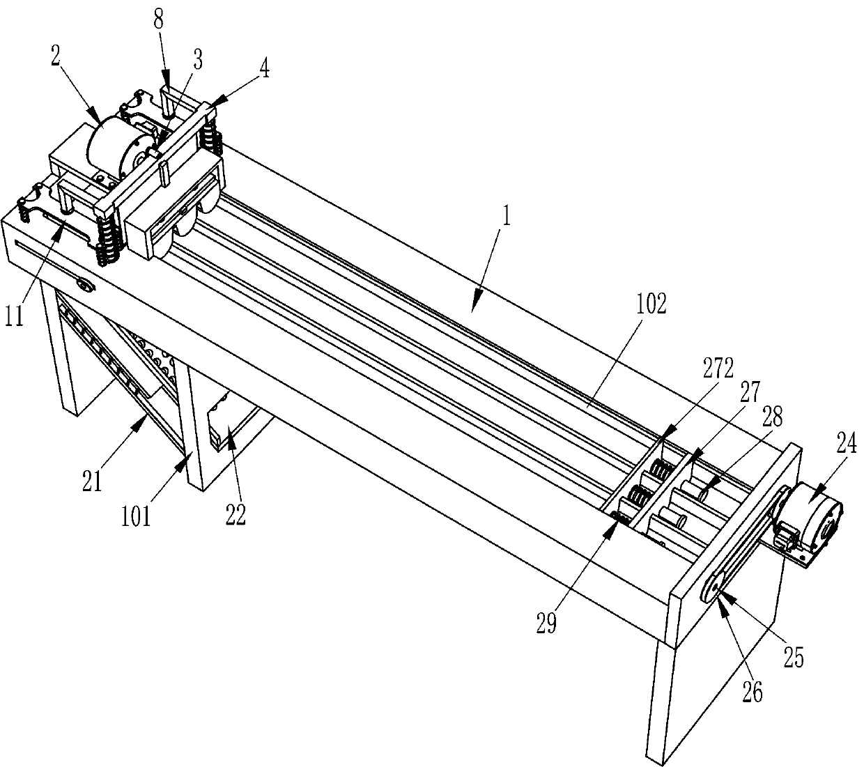
[0026] refer to Figure 1-Figure 6 , a tablet cutting device with adjustable cutting thickness, including a frame 1, legs 101, a cutting mechanism, an adjusting mechanism, a third connecting rod 21, a mesh plate 22 and a fourth connecting rod 23, the bottom left side of the frame 1 A support leg 101 is fixedly connected, and a third connecting rod 21 is fixedly connected between the front and rear sides, the lower part of the left side of the supporting leg 101 and the left side of the frame 1, and the fourth connecting rod 21 is hinged evenly spaced on the left side of the top of the third connecting rod 21. Rod 23, the bottom of supporting leg 101 is slidingly provided with net plate 22, the left end of net plate 22 is in contact with the left side of the bottom of frame 1, and the left part of the front and rear sides of the outer bottom of net plate 22 is also hinged with a fourth connecting rod evenly spaced 23. The ends of the fourth connecting rod 23 on the upper and lo...
Embodiment 2
[0033] refer to figure 1 and figure 2 Compared with Embodiment 1, the main difference of this embodiment is that in this embodiment, it also includes a second motor 24, a second screw mandrel 25, a transmission device 26, a push plate 27, a guide nut 271, a buffer plate 272, a second The telescopic rod 28 and the fifth spring 29 are connected with the second screw mandrel 25 in the front and rear of the frame 1. The second screw mandrel 25 communicates with the placement groove 102. The second screw mandrel 25 is provided with a guide nut through threads. 271, the push plate 27 that cooperates with the placement groove 102 is fixedly connected between the front and rear sides guide nut 271 inner surfaces, and the sliding type that is evenly spaced at the bottom of the push plate 27 is provided with the second telescopic rod 28, and all the second telescopic rods 28 left ends A buffer plate 272 is fixedly connected between them, and the buffer plate 272 cooperates with the pl...
Embodiment 3
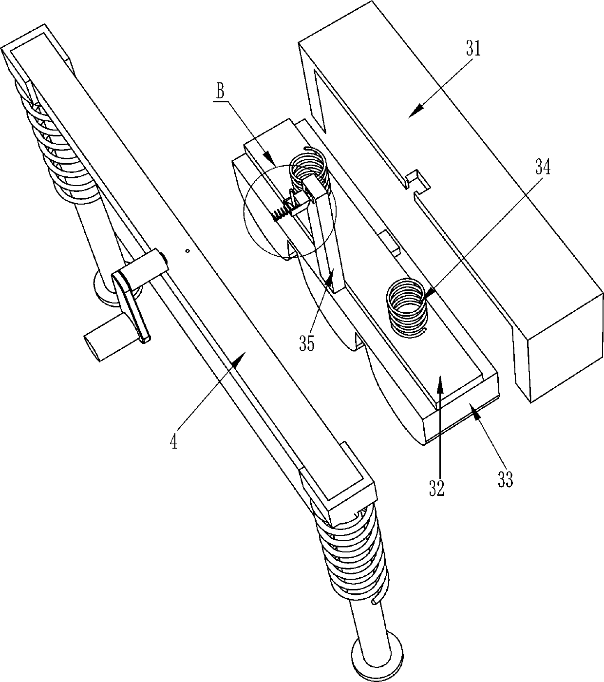
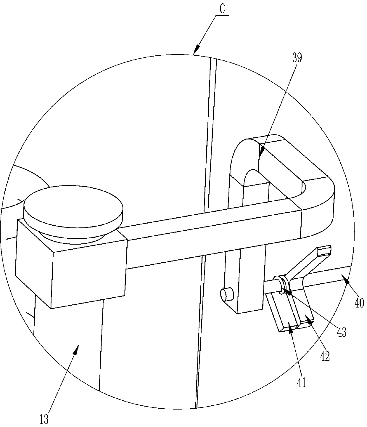
[0036] refer to figure 1 , Figure 7 , Figure 8 , Figure 9 and Figure 10 , the main difference between this embodiment and embodiment 1 and embodiment 2 is that in this embodiment, it also includes a support plate 31, a connecting plate 32, a sponge pressing block 33, a sixth spring 34, an L-shaped telescopic rod 35, a first Two wedge blocks 36, the second pressure bar 37 and the seventh spring 38, the left side of the frame 1 top is fixedly connected with a support plate 31, the support plate 31 is positioned at the right side of the blade 7, and the left side middle part of the support plate 31 top slides. There is an L-shaped telescopic rod 35, and the bottom of the L-shaped telescopic rod 35 is fixedly connected with a connecting plate 32, and the front and rear sides of the top of the connecting plate 32 are connected with the sixth spring 34 between the front and rear sides of the top of the support plate 31, and the bottom of the connecting plate 32 is fixed. The...
PUM
 Abstract
Description
Claims
Application Information
 - R&D
- Intellectual Property
- Life Sciences
- Materials
- Tech Scout
- Unparalleled Data Quality
- Higher Quality Content
- 60% Fewer Hallucinations
Browse by: Latest US Patents, China's latest patents, Technical Efficacy Thesaurus, Application Domain, Technology Topic, Popular Technical Reports.
© 2025 PatSnap. All rights reserved.Legal|Privacy policy|Modern Slavery Act Transparency Statement|Sitemap|About US| Contact US: help@patsnap.com


