Elevator speed governor lifting force testing device and method
A technology of an elevator speed limiter and a test device, which is applied in the field of elevator safety testing, can solve the problems of large space occupied by a roller mechanism, inaccurate test results, waste of laboratory space, etc., so as to save manpower and improve test accuracy and efficiency. , compact structure
Pending Publication Date: 2020-06-16
GUANGDONG INST OF SPECIAL EQUIP INSPECTION
View PDF0 Cites 2 Cited by
- Summary
- Abstract
- Description
- Claims
- Application Information
AI Technical Summary
Problems solved by technology
[0005] The existing speed governor pulling force test device often uses a drum mechanism to stretch the speed governor wire rope. The drum mechanism occupies a large space, and there will be lateral movement during the rotation process, resulting in lateral stress on the speed governor wire rope. lead to inaccurate test results
Aiming at the problem of lateral movement of the drum mechanism, some patents use the addition of pulleys to solve the problem, but the increase in the
Method used
View moreImage
Smart ImageViewing Examples

Examples
 PUM
 Abstract
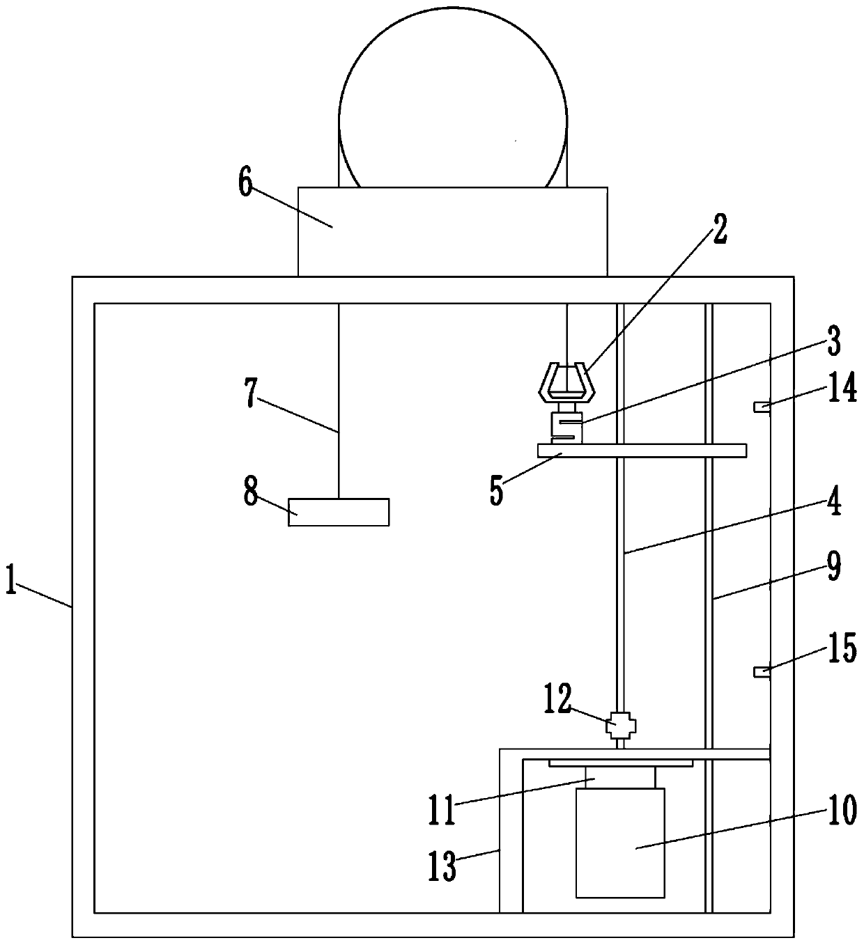
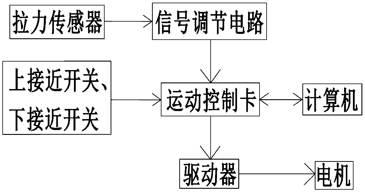
The invention relates to the field of elevator safety detection, and discloses an elevator speed governor lifting force testing device. The elevator speed governor lifting force testing device comprises a testing table, a lifting mechanism, a clamp, a tension sensor and a control system. The lifting mechanism comprises a drive assembly, a lead screw and a movable platform. The lead screw is arranged in the vertical direction, one end of the lead screw is connected with the output end of the drive assembly, the other end of the lead screw is connected with the top of the testing table, and themovable platform is connected with the lead screw through a lead screw nut. The clamp is mounted on the movable platform through the tension sensor, a speed governor is mounted at the top end of the testing table, one end of a steel wire rope of the speed governor is connected with the clamp, and a counter weight is hung at the other end of the steel wire rope of the speed governor. The inventionfurther discloses an elevator speed governor lifting force testing method. The elevator speed governor lifting force testing device and method have the beneficial effects that the structure is reasonable, the operation is convenient, the test is started through one key of a computer, the test result is directly read, and the testing accuracy and efficiency are effectively improved.
Description
technical field [0001] The invention relates to the field of elevator safety detection, in particular to an elevator speed governor lifting force test device and method. Background technique [0002] With the rapid development of my country's economy, the level of manufacturing industry has improved rapidly, and the level of urbanization has continued to accelerate. my country ranks first in the world in terms of elevator manufacturing and inventory. How to improve the production quality of elevator products and how to ensure the safety of elevators in use have become two issues of great concern to my country's elevator industry. [0003] The elevator speed limiter is a very important safety protection device for the elevator, which is responsible for monitoring the speed of the elevator. When the speed of the elevator is out of control, the electrical switch or mechanical action of the speed limiter triggers the action of other protection devices to stop the uncontrolled e...
Claims
Login to View More Application Information
Patent Timeline
 IPC IPC(8): B66B5/04G01L5/00
CPCB66B5/048G01L5/0033
Inventor 王葵张捷洪永潘洪权刘文文孟凡帅代清友佘昆
Owner GUANGDONG INST OF SPECIAL EQUIP INSPECTION
Features
- Generate Ideas
- Intellectual Property
- Life Sciences
- Materials
- Tech Scout
- Unparalleled Data Quality
- Higher Quality Content
- 60% Fewer Hallucinations
Learn More Browse by: Latest US Patents, China's latest patents, Technical Efficacy Thesaurus, Application Domain, Technology Topic, Popular Technical Reports.
© 2025 PatSnap. All rights reserved.Legal|Privacy policy|Modern Slavery Act Transparency Statement|Sitemap|About US| Contact US: help@patsnap.com