Pump body assembly and compressor

A technology of compressors and components, which is applied in the field of compressors and can solve problems such as compressor performance impact

Active Publication Date: 2020-06-16
GUANGDONG MEIZHI PRECISION MFG
View PDF7 Cites 5 Cited by
  • Summary
  • Abstract
  • Description
  • Claims
  • Application Information

AI Technical Summary

Problems solved by technology

The light weight of the balance weight is beneficial to solve the problem of wear on the upper end of the crankshaft. However, the quality of the balance weight depends on the mass of its eccentric part, and its balance effect directly affects the vibration and noise indicators of the com

Method used


Image

  • Pump body assembly and compressor
  • Pump body assembly and compressor
  • Pump body assembly and compressor

Examples


Embodiment 1

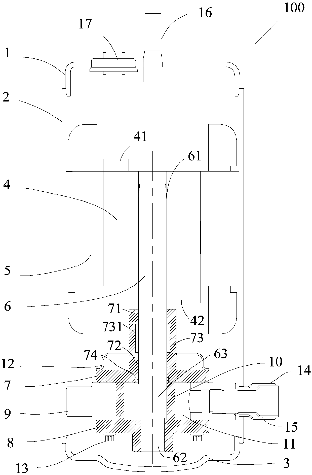
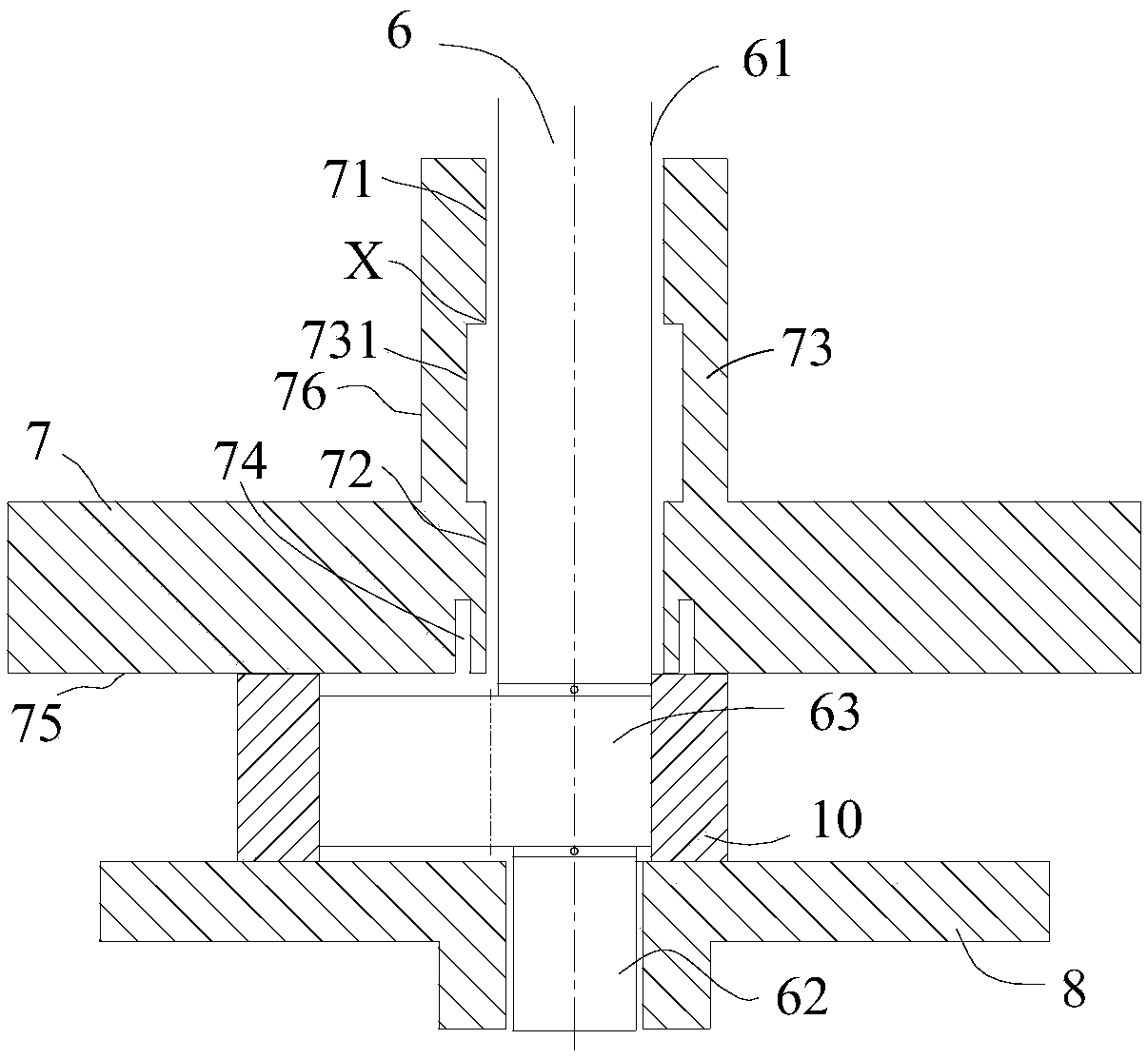
[0136] Such as Figure 1 to Figure 3 As shown, the pump body assembly includes a crankshaft 6, a first bearing 8 and a second bearing 7, one end of the crankshaft 6 is used to connect the motor of the compressor 100; the first bearing 8 is sleeved on the other end of the crankshaft 6; the second bearing 7 Sleeved on the crankshaft 6, the second bearing 7 includes a first bearing segment 71, a gap bearing segment 73 and a second bearing segment 72 which are sequentially connected from top to bottom; wherein, the inner side wall of the gap bearing segment 73 is provided with a bearing recess Groove 731 , the second bearing 7 also includes a second bearing annular groove 74 surrounding the crankshaft 6 , the second bearing annular groove 74 is located on the end wall of the second bearing section 72 facing the first bearing 8 , that is, the second bearing bottom wall 75 .

[0137] Such as Figure 9 As shown, when the compressor is running, the crankshaft 6 is subject to the cent...

Embodiment 2

[0149] Such as Figure 4 with Figure 5 As shown, the structure of this embodiment is substantially the same as that of Embodiment 1, the only difference is that the groove of Embodiment 1 is on the second bearing 7 and divides the second bearing 7 into a first bearing segment 71 and a second bearing segment 72 In this embodiment, the groove is arranged on the crankshaft 6, so that the main shaft 61 corresponding to the crankshaft 6 and the second bearing 7 is divided into the first main shaft section 611, the second main shaft section 613 and the crankshaft recess formed between them. Groove 612. The compressor 100 provided in Embodiment 2, based on the same principle as Embodiment 1, can improve the wear of the upper end of the second bearing 7 and the root of the second bearing 7, reduce the viscous resistance loss of the compressor 100, and improve the performance of the compressor 100. efficiency.

[0150] The geometric constraints and lubrication conditions defined in...

Embodiment 3

[0153] Such as Figure 6 As shown, the structure of this embodiment is substantially the same as that of Embodiment 2. On the basis of Embodiment 2, this embodiment adds a first bearing annular groove 81 to the first bearing 8 . The compressor 100 provided by Embodiment 3, based on the same principle as Embodiment 1 and Embodiment 2, can improve the wear of the upper end of the second bearing 7 and the root of the second bearing 7 and the root of the first bearing 8, and reduce the wear of the compressor 100. The viscous resistance loss improves the energy efficiency of the compressor 100 .

[0154] The geometric constraints and lubrication conditions defined in Embodiment 1 and Embodiment 2 are still applicable in Embodiment 3. In addition, the lubrication conditions to be satisfied by the first bearing annular groove 81 are:

[0155]

[0156] in,

[0157]

[0158] Such as figure 1 , Figure 4 with Figure 6 As shown, the embodiment of another aspect of the prese...


PUM


Abstract

The invention provides a pump body assembly and a compressor. The pump body assembly comprises a motor, a crankshaft, a first bearing and a second bearing, wherein one end of the crankshaft is used for being connected with the motor, the first bearing is arranged on the other end of the crankshaft in a sleeving mode, and the second bearing is arranged on the crankshaft in a sleeving mode; the second bearing comprises a first bearing section, a clearance bearing section and a second bearing section which are connected in sequence, and the second bearing section is connected to the end, facing the first bearing, of the clearance bearing section; the second bearing further comprises a second bearing annular groove surrounding the crankshaft, and the second bearing annular groove is located inthe end wall, facing the first bearing, of the second bearing section; and a groove is formed in the inner side wall of the clearance bearing section, or a groove is formed in the peripheral wall, corresponding to the clearance bearing section, of the crankshaft. According to the pump body assembly, through the arrangement of the groove, viscous resistance loss can be reduced, and lubrication ofthe upper end of the second bearing can be improved; and through the arrangement of the second bearing annular groove, the root abrasion of the second bearing can be improved.

Description

technical field [0001] The present invention relates to the technical field of compressors, in particular to a pump body assembly and a compressor. Background technique [0002] It is pointed out in the related art that the upper end of the crankshaft and / or the root of the crankshaft of the rotary compressor are prone to wear after long-term operation. In order to improve the performance of the compressor, it has become a development trend to design the compressor with a small shaft diameter, which will further increase the risk of crankshaft wear. [0003] Research shows that the wear on the upper end of the crankshaft is mainly related to the centrifugal force of the balance weight, and the wear on the root of the crankshaft is mainly related to the gas force load. The light weight of the balance weight is beneficial to solve the problem of wear on the upper end of the crankshaft. However, the quality of the balance weight depends on the mass of its eccentric part, and i...

Claims


Application Information

Patent Timeline
IPC IPC(8): F04C23/02F04C29/00
CPCF04C23/02F04C29/0042F04C29/00F04C2240/50F04C2240/60
Inventor 吕林波
Owner GUANGDONG MEIZHI PRECISION MFG
Why Eureka
Try Eureka