Device and method for measuring excitation force of camshaft to camshaft bearing cover

A technology of cam bearings and measuring devices, applied in measuring devices, force/torque/work measuring instruments, force sensors related to bearings, etc., can solve the problem of large force errors in strain gauge measurement, inability to obtain force values, and excitation Complex force and other problems, to achieve accurate measurement, not easy to be disturbed, precise boundary conditions

Active Publication Date: 2020-06-16
CHINA FIRST AUTOMOBILE
View PDF23 Cites 2 Cited by
  • Summary
  • Abstract
  • Description
  • Claims
  • Application Information

AI Technical Summary

Problems solved by technology

[0005] 1. When the camshaft rotates, the force on the cam bearing seat is always changing, so the excitation of the camshaft to the cam bearing cover is also multi-directional, including vertical and horizontal forces, as well as bending forces. The strain gauges are located on both sides of the outer sides of the bearing cap, and what they measure is the final resultant force signal, and the force value corresponding to each force direction cannot be obtained;
[0006] 2. Since the strain gauge is a measuring element that responds to the stress situation through force deformation, it is affected by many factors such as vibration, temperature, and sticking direction, while the excitation force of the camshaft on the cam bearing cover is more complicated, and the frequency of change is relatively high. High, so the force error measured by the strain gauge is large;

Method used


Image

  • Device and method for measuring excitation force of camshaft to camshaft bearing cover
  • Device and method for measuring excitation force of camshaft to camshaft bearing cover

Examples


specific Embodiment approach

[0052] In order to clearly and completely describe the technical solution of the present invention and its specific working process, in conjunction with the accompanying drawings, the specific implementation of the present invention is as follows:

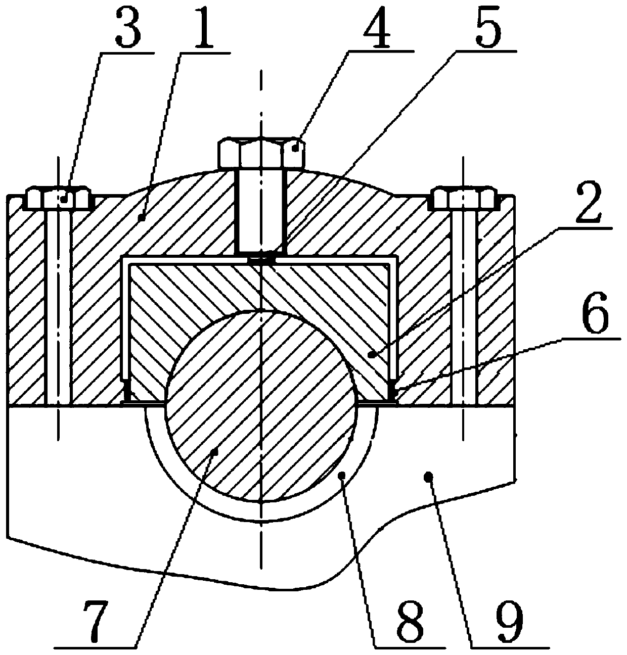
[0053] Such as figure 1 As shown, the present invention discloses a camshaft-to-cam bearing cover excitation force measuring device, which includes an outer member 1, an inner member 2, a fastening bolt 3, an adjustment bolt 4, a vertical pressure sensing plate 5 and a horizontal pressure sensing slice 6.

[0054] The camshaft 7 is directly installed in the cam bearing seat 8, so that the first circumferential surface of the camshaft 7 is matched with the arc surface in the installation groove of the cam bearing seat 8, and the cam bearing seat 8 is arranged on the engine cylinder head 9, and the cam The upper surface of the bearing seat 8 is flush with the connecting surface on the engine cylinder head 9;

[0055] The inner surf...


PUM


Abstract

The invention provides a device and a method for measuring excitation force of a cam shaft on a cam bearing cover. The device takes an existing cam bearing cover as a prototype, is divided into an inner component and an outer component, and is provided with pressure sensing sheets in the horizontal direction and the vertical direction between the inner component and the outer component; the two sides of the horizontal pressure sensing piece make plane contact with the inner component and the outer component respectively, the vertical pressure sensing piece is pre-tightened to the top part of the inner component through using an adjusting bolt at the top part of the outer component, thereby guaranteeing that the excitation force of the cam shaft is accurately transmitted to the pressure sensing piece by adjusting the position relation among the outer component, the inner component, the adjusting bolt and the pressure sensing piece. According to the method, the measuring device is adopted to collect the excitation force generated by the cam shaft in the horizontal direction and the vertical direction respectively, signals output by the pressure sensing piece are converted according to the calibrated relation, and stress data can be obtained. The device and the method can be used for measuring the stress of the cam bearing cover in the horizontal direction and the vertical direction accurately , so as to accurately reflect the excitation force of the cam shaft on the cam bearing cover.

Description

technical field [0001] The invention belongs to the technical field of force measurement of engine parts, in particular to a device and method for measuring the excitation force of a camshaft to a cam bearing cap. Background technique [0002] When an ordinary engine is upgraded to a supercharged engine, the strength of its components will face a more severe test. When the engine is working, the cam bearing seat and the bearing cover are one of the most dangerous parts, and the strength of these parts determines the reliability of the engine cylinder head. [0003] With the improvement of national regulations and customer requirements, the engine's NVH (Noise, Vibration, Harshness, that is, noise, vibration and harshness) performance has attracted more and more attention. The excitation of the camshaft to the cam bearing cover is one of the important excitation sources of engine noise radiation. Therefore, the accuracy of the input excitation force of the camshaft to the ca...

Claims


Application Information

Patent Timeline
Patent Type & Authority Applications(China)
IPC IPC(8): G01L5/00
CPCG01L5/0009
Inventor 李天成蒋文虎董爽胡伟兴胡福尚刘晓光吴仁哲解小凯
Owner CHINA FIRST AUTOMOBILE
Why Eureka
Try Eureka