
Comprehensive system for measuring conduction and radiation characteristics of packaged antenna

A radiation characteristic and integrated system technology, applied in the antenna radiation pattern and other directions, can solve the problems of delaying the development schedule of the packaged antenna, the test schedule of the packaged antenna cannot be further shortened, and the measurement of the radiation characteristic parameters cannot be performed at the same time, so as to shorten the development time The effect of timing

Active Publication Date: 2020-06-16
JTHINK TECH +1
View PDF16 Cites 6 Cited by
  • Summary
  • Abstract
  • Description
  • Claims
  • Application Information

AI Technical Summary

Problems solved by technology

[0004] In this way, when the antenna-in-package is installed on the traditional package test base, only the conductive electrical test can be performed, and the radiation characteristic parameter measurement cannot be performed at the same time; on the other hand, the overall Machine OTA parameter measurement, if the performance is found to be poor after the OTA test, the design of the packaged antenna must be modified, and the packaged antenna after the modified design must be reinstalled on the traditional package test base for conductive electrical testing, and then another Installed into the radiation characteristic test device for OTA parameter measurement
[0005] To sum up, due to the functional limitation of the traditional package test base, it can only be used for conducting electrical tests, and in order to measure the parameters of the radiation characteristics of the package antenna, it is necessary to use a radiation characteristic test device
Separately measure conductive electrical parameters and radiation characteristic parameters through the traditional package test base and radiation characteristic test device. Overall, the detection time of the package antenna cannot be further shortened, and the development time of the package antenna is relatively delayed.

Method used


Image

  • Comprehensive system for measuring conduction and radiation characteristics of packaged antenna
  • Comprehensive system for measuring conduction and radiation characteristics of packaged antenna
  • Comprehensive system for measuring conduction and radiation characteristics of packaged antenna

Examples


Embodiment Construction

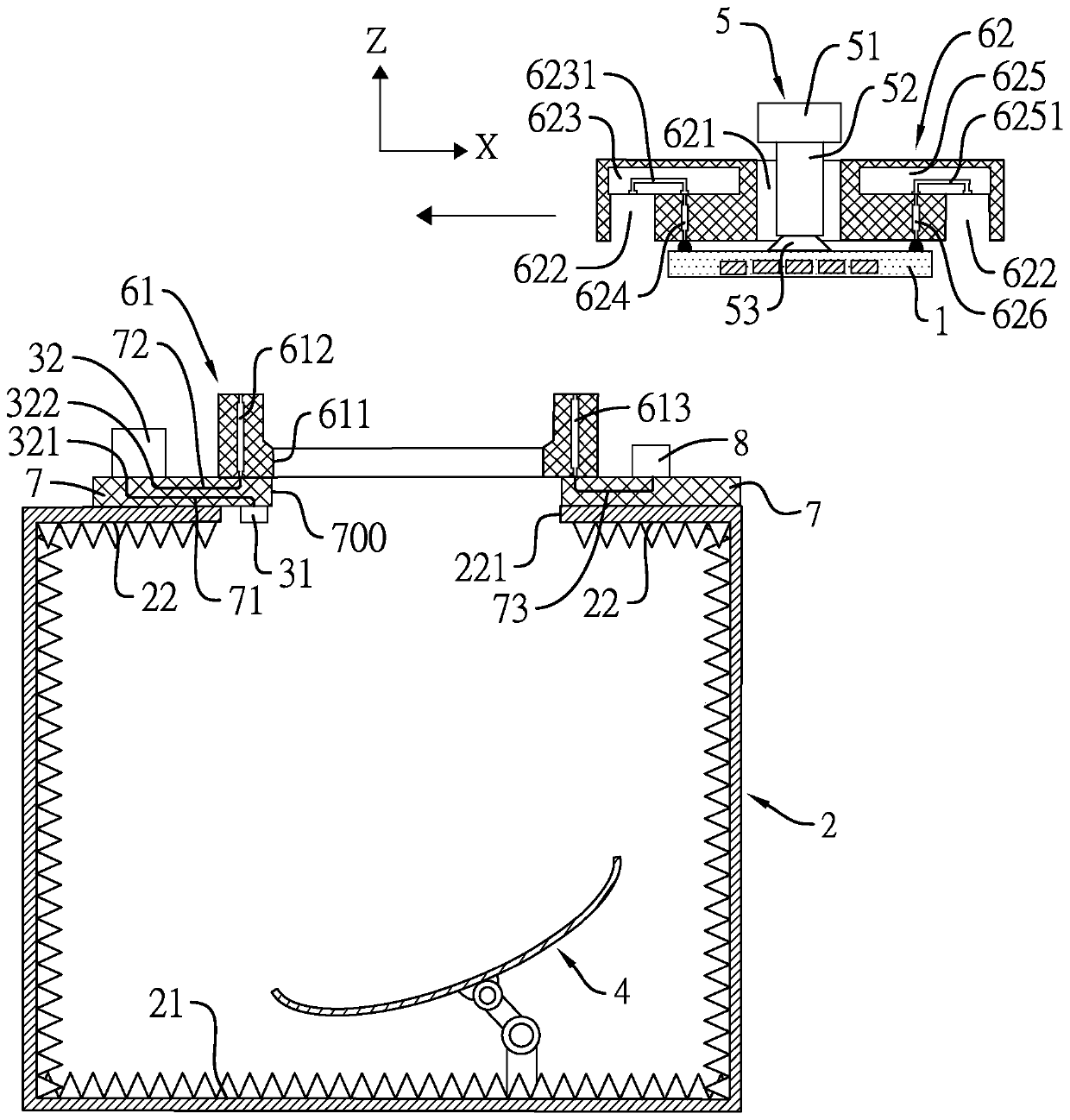
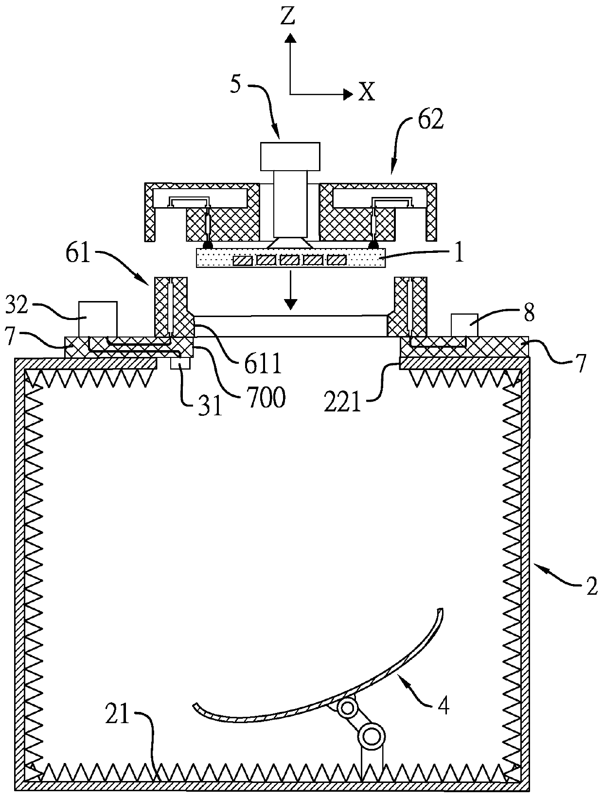
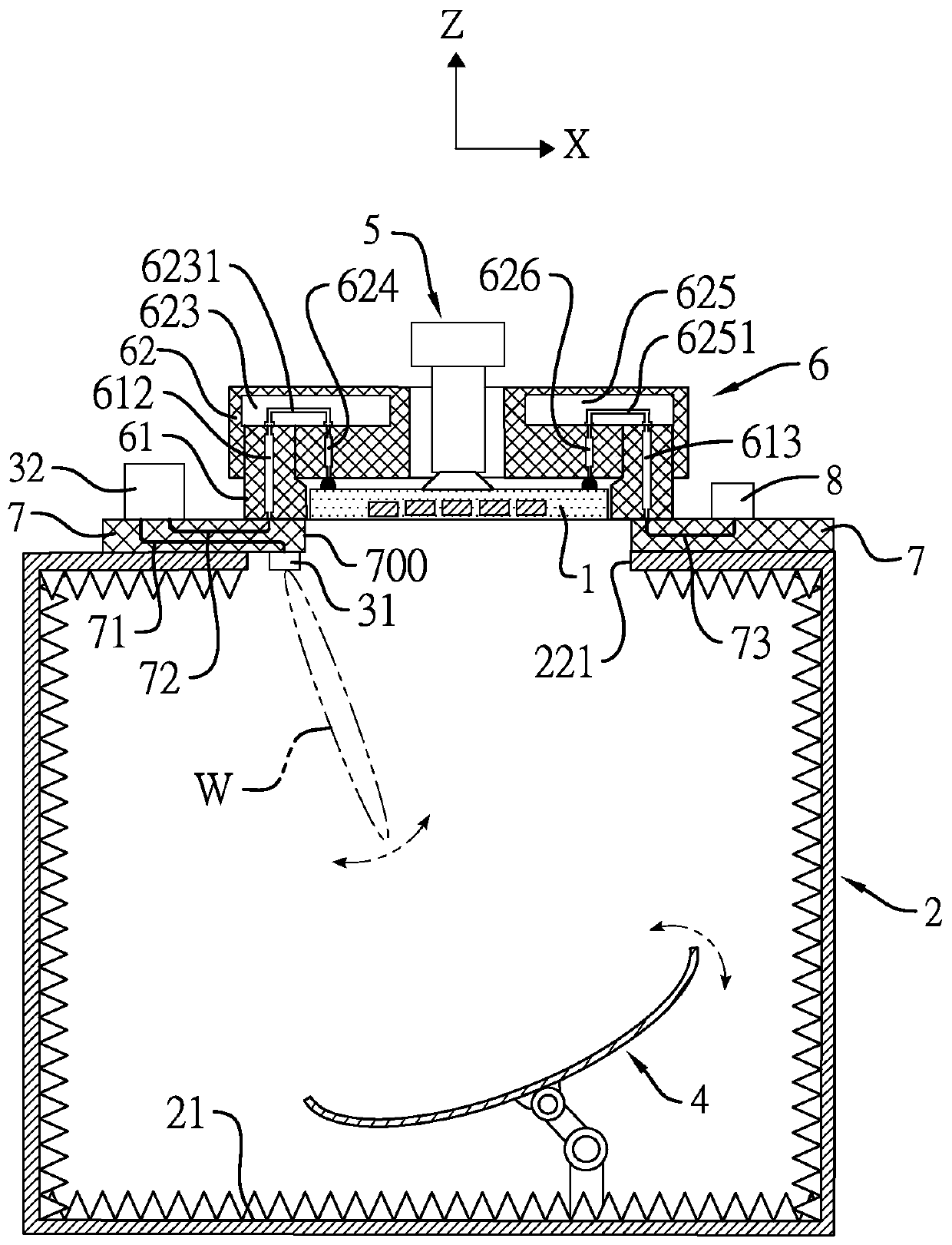
[0029] Refer to Figure 1 to Figure 3 The integrated system of the present invention for measuring the conduction and radiation characteristics of a packaged antenna is used to measure a packaged antenna 1. The preferred embodiment of the present invention includes a microwave anechoic chamber 2, a radio frequency measurement unit, a chip suction device 5, and a The package test base 6 or, in other embodiments, the integrated system of the present invention may further include a reflector 4, a test carrier 7 and / or a fundamental frequency measurement device 8. For convenience of description, the present invention Figure 1 to Figure 3 and Figure 5 All present the structure of the microwave anechoic chamber 2, the radio frequency measurement unit, the chip suction device 5, the packaging test base 6, the reflector 4, the test carrier 7 and the fundamental frequency measurement equipment 8.

[0030] The microwave anechoic chamber 2 includes a floor 21 and a top plate 22 that face...


PUM


Abstract

The invention discloses a comprehensive system for measuring conduction and radiation characteristics of a packaged antenna. The comprehensive system comprises a microwave anechoic chamber, radio frequency measurement equipment, a feed source antenna, a chip suction device and a packaged test base, wherein the package testing base comprises a first base part and a second base part which can be jointed or separated; the first base part is fixedly arranged above a top plate of the microwave anechoic chamber; the chip suction device penetrates through a through hole defined by the second base part; the chip suction device is linked with the second base part; when the second base part is jointed with the first base part, the radio frequency measurement equipment is electrically connected withthe packaged antenna by means of the first base part and the second base part in sequence, so as to measure radio frequency conduction characteristic parameters of the packaged antenna; and the radiofrequency measurement equipment is further electrically connected with the feed source antenna so as to measure the radiation characteristics of the packaged antenna.

Description

Technical field [0001] The invention relates to a measurement system, in particular to a comprehensive system for measuring the conduction and radiation characteristics of a packaged antenna. Background technique [0002] With the evolution and diversified applications of mobile communication technology, there is an existing antenna module that integrates an antenna into a chip package, called "Antenna in Package (AiP)". In the development process of the packaged antenna, a package test base (SKT) needs to be used to detect the conductive electrical parameters of the packaged antenna. During testing, the packaged antenna is set on the packaged test base, and the pins of the packaged antenna are directly contacted with the probe to form an electrical connection with the packaged antenna, and then the test signal is transmitted and measured to Conduct the electrical conductivity test of the packaged antenna. [0003] In practice, the packaged antenna not only needs to be tested for...

Claims


Application Information

Patent Timeline
IPC IPC(8): G01R29/10
CPCG01R29/10
Inventor 黄荣书叶柏榕苏胜义乔鸿培李子胜蔡宪毅吴俞宏邱宗文
Owner JTHINK TECH
Learn More