Ultrasonic diagnostic apparatus

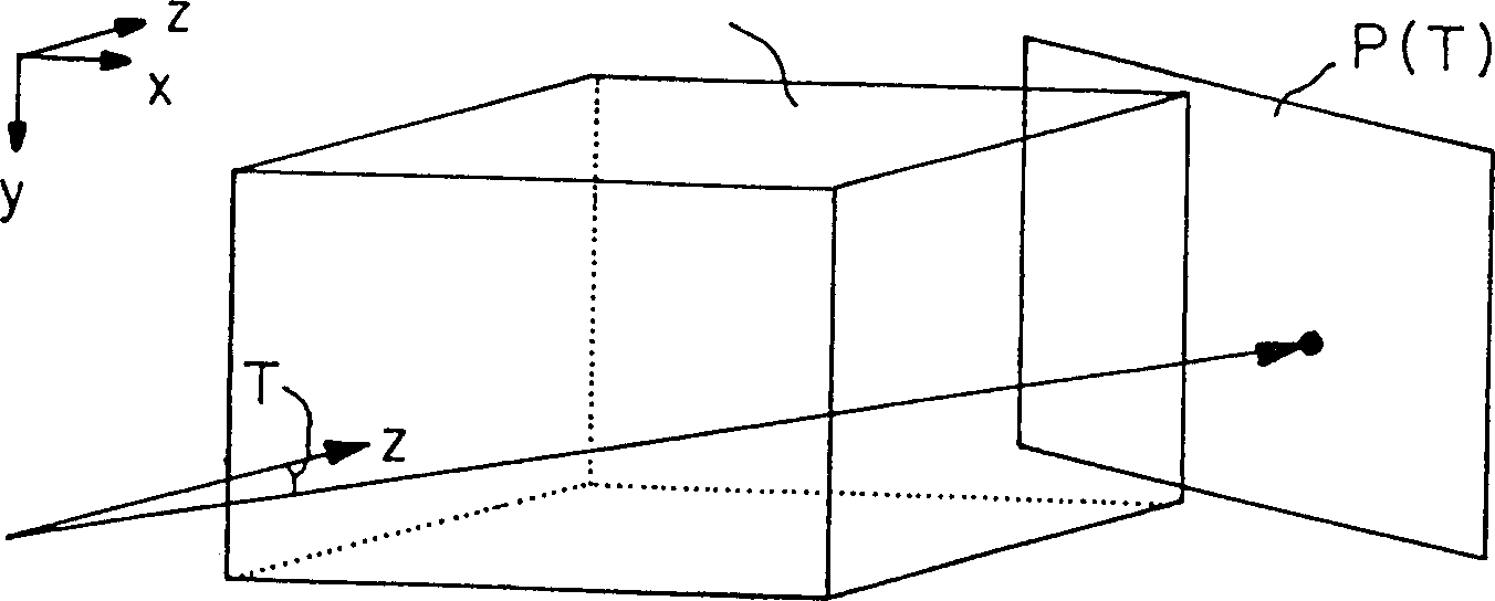
A diagnostic equipment, ultrasonic technology, applied in the direction of acoustic wave diagnosis, infrasonic wave diagnosis, ultrasonic/sonic wave/infrasonic wave diagnosis, etc., can solve the problem of complex structure of traditional systems, difficulty in determining, three-dimensional ultrasonic image cannot reflect the distance between the ultrasonic probe 1 and the target object, etc. question

Inactive Publication Date: 2003-07-02
GE YOKOGAWA MEDICAL SYST LTD
View PDF5 Cites 6 Cited by
  • Summary
  • Abstract
  • Description
  • Claims
  • Application Information

AI Technical Summary

Problems solved by technology

[0006] A disadvantage of the traditional ultrasonic diagnostic system is that the displayed three-dimensional ultrasonic image cannot reflect the distance between the ultrasonic probe 1 and the target object
When operating such a system, it is difficult for the operator to determine how far the targ

Method used


Image

  • Ultrasonic diagnostic apparatus
  • Ultrasonic diagnostic apparatus
  • Ultrasonic diagnostic apparatus

Examples


no. 1 example

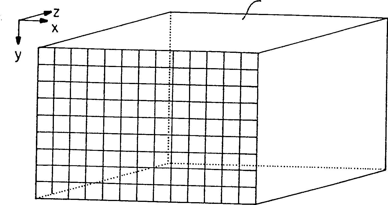
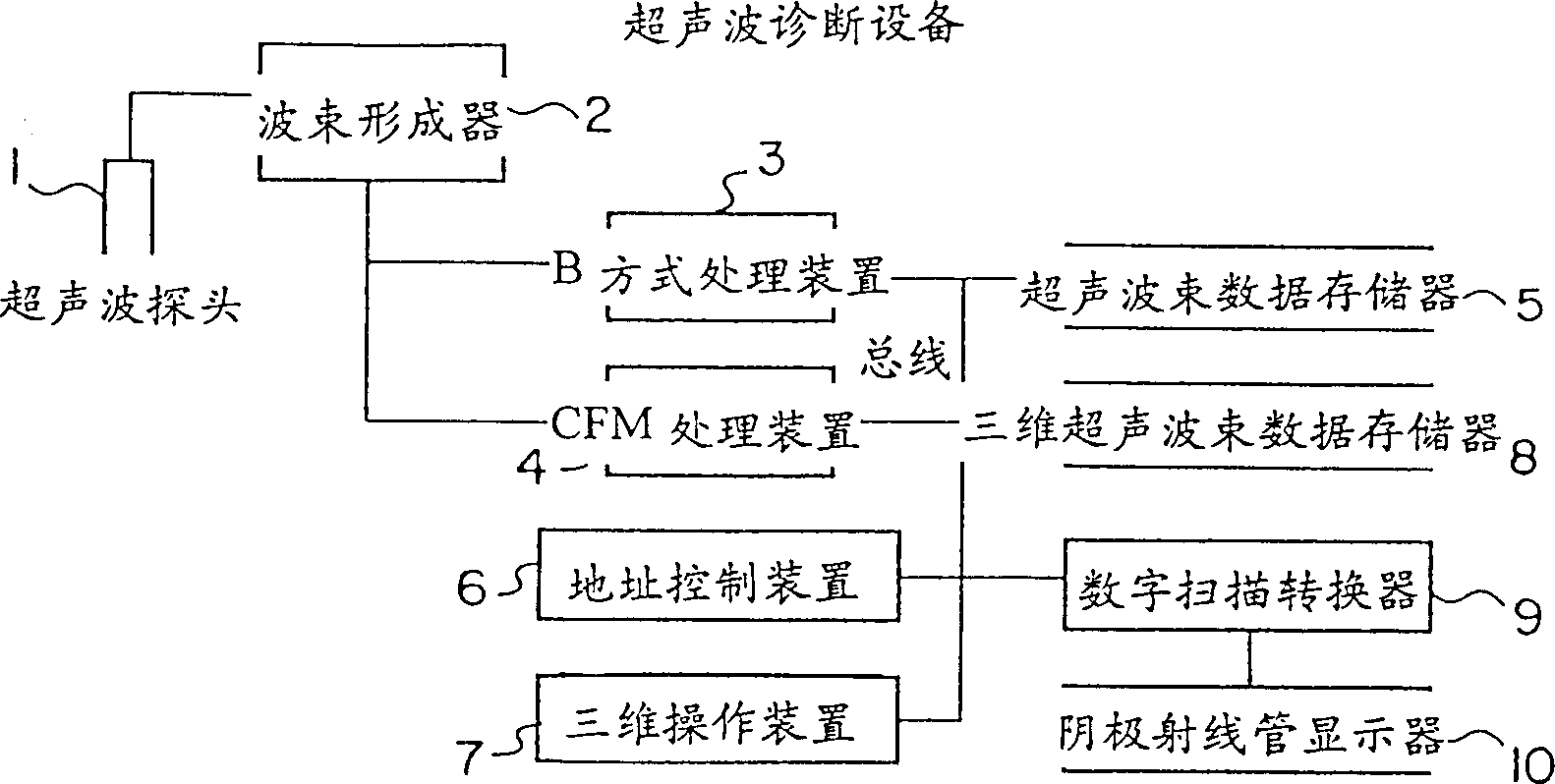
[0053] image 3 An ultrasonic diagnostic apparatus implemented according to a first embodiment of the present invention is sketched. exist image 3 Among them, an ultrasonic diagnostic apparatus 100 includes an ultrasonic probe 1 and an ultrasonic beamformer 2 . The ultrasonic probe 1 transmits ultrasonic pulses to a target object and receives ultrasonic echoes reflected from the target object. The ultrasonic beamformer 2 changes the directions of the ultrasonic beams so as to scan a plane within the target object, and generates signals of the ultrasonic beams in each beam direction. In addition, in the ultrasonic diagnostic equipment 100, the B mode processing device 3 generates B mode ultrasonic beam data according to the intensity of the ultrasonic beam signal; the CFM mode processing device 4 generates CFM mode ultrasonic beam data according to the Doppler component in the ultrasonic beam signal; The beam data memory (cine memory) 5 stores the ultrasonic beam data (that i...

no. 2 example

[0074] Figure 11 is a block diagram of an ultrasonic diagnostic apparatus 200 practiced according to a second embodiment of the present invention. In operation, the ultrasonic diagnostic apparatus 200 reads out the ultrasonic beam data from the ultrasonic beam data memory 5 for input into the three-dimensional operation device 21, and at the same time reads out the three-dimensional ultrasonic beam data from the three-dimensional ultrasonic beam data memory 8, and reads out the ultrasonic beam data corresponding to the read out ultrasonic beam data. The three-dimensional operation is performed together with the beam data, which is also input into the three-dimensional operation device 21. The three-dimensional manipulation means 21 is a look-up table (LUT) built in RAM or ROM.

[0075] After the ultrasonic beam data is accumulated in the ultrasonic beam data memory 5, a three-dimensional display command can be issued. This enables the second embodiment, like the first embod...

no. 3 example

[0079] Figure 12 is a block diagram of an ultrasonic diagnostic apparatus 300 practiced according to a third embodiment of the present invention. The ultrasonic diagnostic apparatus 300 has a local circuit memory 32 built in the three-dimensional manipulation unit 21 . Using the local line memory 32, the three-dimensional operation device 21 performs three-dimensional operations at a higher speed than before.


PUM


Abstract

An ultrasonic diagnostic apparatus either for displaying three-dimensional ultrasonic images allowing an operator to become aware of the distance of a target object from an ultrasonic probe (1), or for displaying practical three-dimensional ultrasonic images while being simply structured and taking a short time to perform necessary operations. The apparatus comprises: an ultrasonic beam data memory (5) for storing B-mode ultrasonic beam data or CFM ultrasonic beam data; an address control unit (6) for sequentially writing and reading the ultrasonic beam data to and from the ultrasonic beam data memory in the direction of depth; a three-dimensional operation unit (7) for generating three-dimensional ultrasonic beam data using the ultrasonic beam data read from the ultrasonic beam data memory by the address control unit; a three-dimensional ultrasonic beam data memory (8) for storing the three-dimensional ultrasonic beam data thus generated; a DSC (digital scan converter) (9) for converting the three-dimensional beam data to a display-ready format; and a CRT (10).

Description

technical field [0001] The present invention relates to an ultrasonic imaging method and ultrasonic diagnostic equipment, and more particularly, the present invention relates to an ultrasonic imaging method and ultrasonic diagnosis for displaying a three-dimensional ultrasonic target object image, allowing the operator to grasp the distance between the ultrasonic probe and the imaged object equipment, the ultrasonic diagnostic equipment has a simple structure, but can display practical three-dimensional ultrasonic images in a short operation time. Background technique [0002] In order to provide a three-dimensional display of ultrasound images, it involves scanning the inner plane (represented by frames) of the target object with an ultrasound probe. The ultrasound probe is moved in a direction substantially perpendicular to the plane to accumulate ultrasound beam data representing a plurality of frames. [0003] FIG. 1 is a conceptual view of volume data Vo1. A digital s...

Claims


Application Information

Patent Timeline
IPC IPC(8): G01N29/06A61B8/00G01S15/89
CPCG01N29/0609Y10S128/916G01N2291/02854G01S15/8993G01S15/8945A61B8/00G01S15/89
Inventor 雨宫慎一桥本浩见山广二加藤生
Owner GE YOKOGAWA MEDICAL SYST LTD
Why Eureka
Try Eureka