Access system of industrial control equipment
An industrial control and access system technology, applied in the direction of instruments, electrical digital data processing, digital data processing components, etc., can solve the problems of high working electrical filtration, high temperature of machines, and poor dust prevention, so as to reduce manpower The effect of the operation
- Summary
- Abstract
- Description
- Claims
- Application Information
AI Technical Summary
Problems solved by technology
Method used
Image

Examples
Embodiment
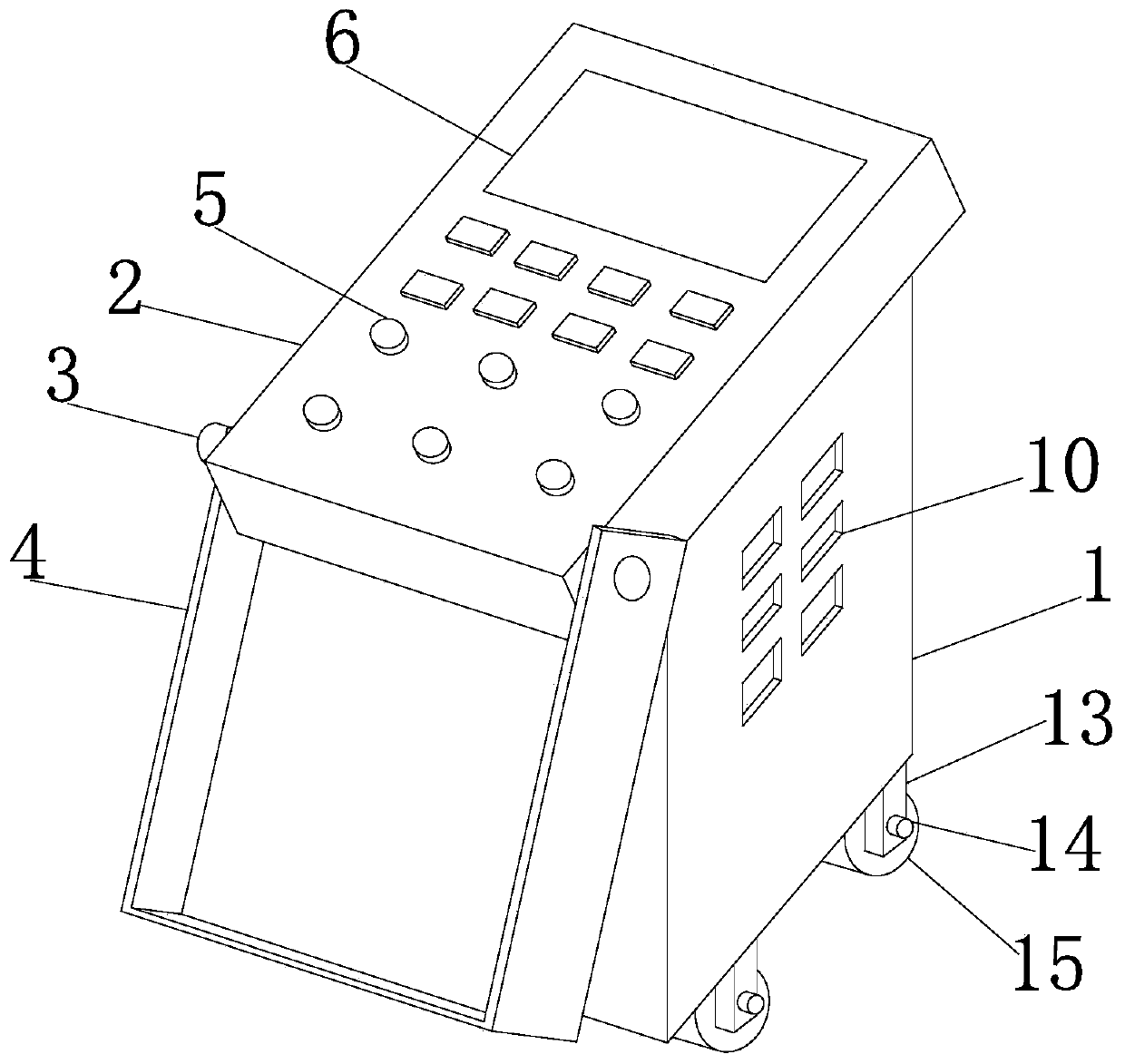
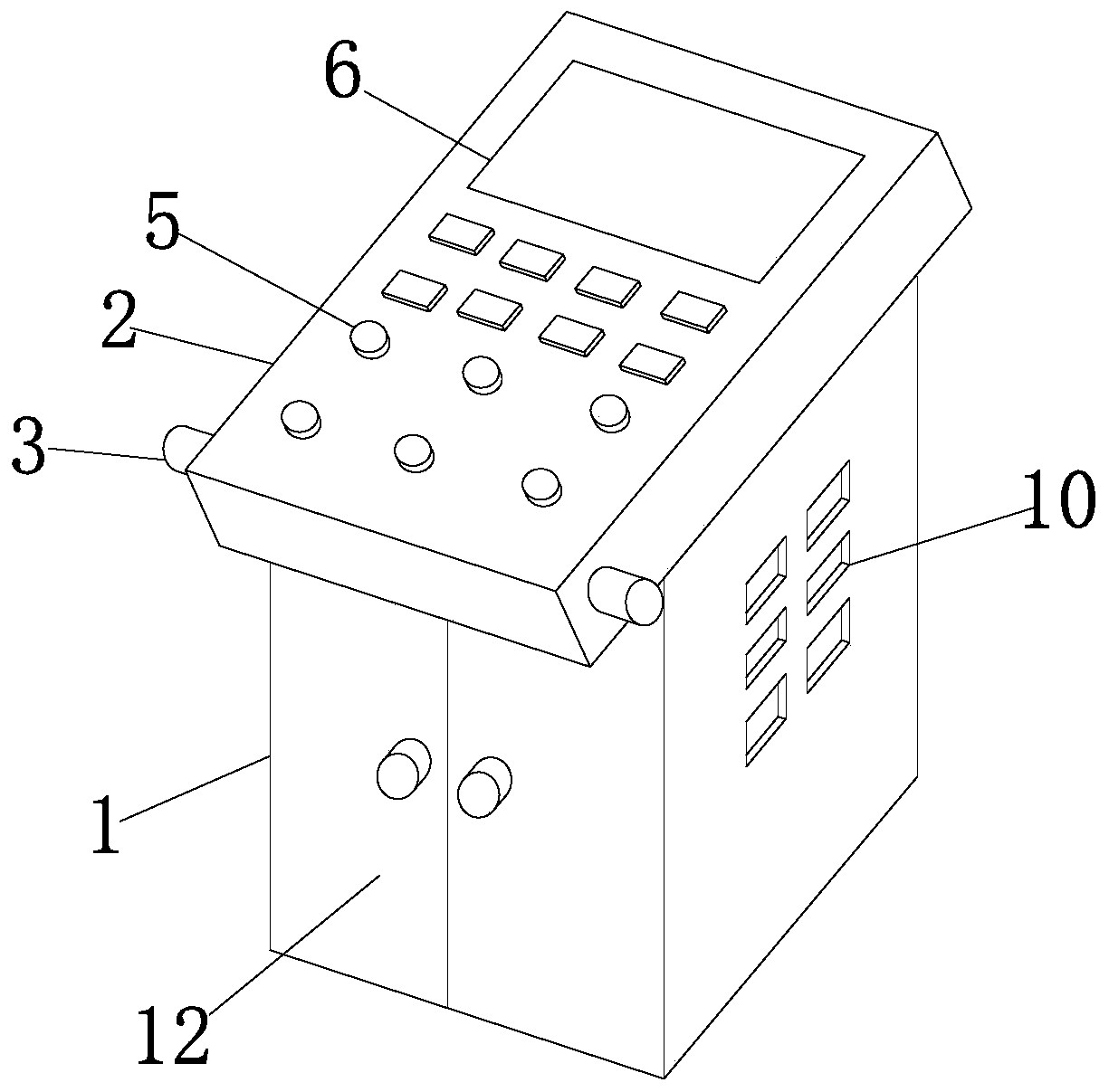
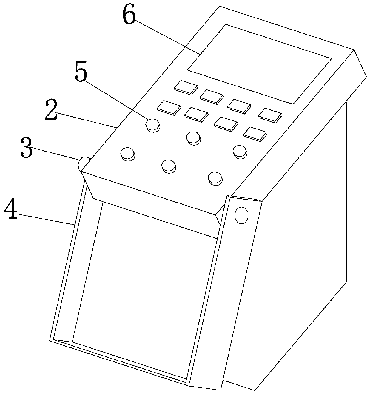
[0030] Embodiment: a kind of access system of industrial control equipment, such as Figure 1-Figure 7As shown, it includes an equipment control cabinet 1. The equipment control cabinet 1 is a rectangular equipment control cabinet. An operation console 2 is fixedly and movably connected to the top of the equipment control cabinet 1. The operation console 2 is a rectangular inclined The operation console, the position behind the left end wall of the operation console 2 is fixedly equipped with a movable shaft 3, the movable shaft 3 is a circular movable shaft, and the movable shaft 3 runs through the left wall of the operation console 2 and extends all the time Outside the right wall surface of the operation console 2, the left side of the movable shaft 3 and the outer circle of the right side of the movable shaft 3 are fixedly equipped with a rotating dustproof cover 4, and the rotating dustproof cover 4 is a rectangular rotating dustproof cover. A dust cover device, and the i...
PUM
 Abstract
Description
Claims
Application Information
 - Generate Ideas
- Intellectual Property
- Life Sciences
- Materials
- Tech Scout
- Unparalleled Data Quality
- Higher Quality Content
- 60% Fewer Hallucinations
Browse by: Latest US Patents, China's latest patents, Technical Efficacy Thesaurus, Application Domain, Technology Topic, Popular Technical Reports.
© 2025 PatSnap. All rights reserved.Legal|Privacy policy|Modern Slavery Act Transparency Statement|Sitemap|About US| Contact US: help@patsnap.com