
A high-speed spin-wave waveguide based on magnetic dipole interaction

A technology of spin wave and magnetic dipole, applied in the direction of waveguide, waveguide-type devices, circuits, etc., can solve the problems of complex manufacturing process of double-layer waveguide, difficult docking, unfavorable development of spin wave devices, etc., and is conducive to miniaturization , simple preparation process and wide application scenarios

Active Publication Date: 2022-03-15
UNIV OF ELECTRONICS SCI & TECH OF CHINA
View PDF1 Cites 0 Cited by
  • Summary
  • Abstract
  • Description
  • Claims
  • Application Information

AI Technical Summary

Problems solved by technology

But there are the following disadvantages: First, the spin wave acceleration based on the exchange coupling effect is realized by inducing a hybridization mode spin wave at the interface of the ferrimagnetic-ferromagnetic layer. The properties of the spin wave in the study are not exactly the same as those in the previous research, which is not conducive to the development of spin wave devices using the research results of the past few decades; secondly, the double-layer structure waveguide has the same There are also difficulties in the docking of spin-wave functional devices, because most spin-wave functional devices are planar structures; finally, the fabrication process of this double-layer waveguide in the vertical direction is also relatively complicated

Method used


Image

  • A high-speed spin-wave waveguide based on magnetic dipole interaction
  • A high-speed spin-wave waveguide based on magnetic dipole interaction
  • A high-speed spin-wave waveguide based on magnetic dipole interaction

Examples


Embodiment

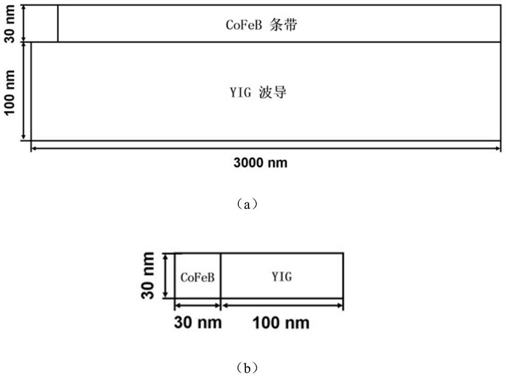
[0027] In this embodiment, the material of the ferrimagnetic rectangular strip is yttrium iron garnet (YIG), which has an extremely low Gilbert damping coefficient, and using it as a medium for spin wave transport greatly improves the propagation of spin waves distance. The specific parameters of the material are: saturation magnetization Ms=1.4×10 5 A / m, exchange constant A=3.5×10 -12 J / m, Gilbert damping coefficient α=2×10 -4 . The material of the ferromagnetic rectangular strips is CoFeB, which has a large saturation magnetization. Specific parameters of the material: saturation magnetization Ms=1.15×10⁶ A / m, exchange constant A=1.6×10 -11 J / m, Gilbert damping coefficient α=5×10 -3 . The specific shape parameters of the spin-wave waveguide are as follows: figure 1 Shown: the length of the YIG waveguide is 3000nm, the width is 100nm, and the thickness is 30nm, and the length of the CoFeB strip is 2800nm, the width is 30nm, and the thickness is 30nm.

[0028] figure...


PUM

PropertyMeasurementUnit
thicknessaaaaaaaaaa
saturation magnetizationaaaaaaaaaa

Abstract

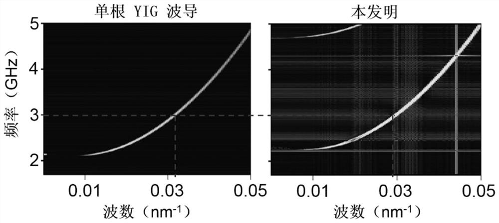
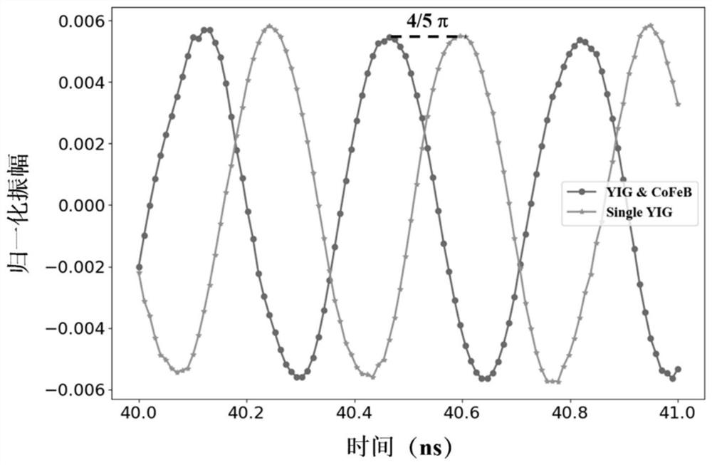
The invention relates to a high-wave-speed spin-wave waveguide based on magnetic dipole action, which belongs to the technical field of magnon devices. The spin wave waveguide includes a ferrimagnetic rectangular strip and a ferromagnetic rectangular strip located on one side of the ferrimagnetic rectangular strip, the ratio of the length to width of the ferrimagnetic rectangular strip is greater than 25, and the thickness is 10 ~50nm, the width of the ferromagnetic rectangular strip is 1 / 4~1 / 2 of the width of the ferrimagnetic rectangular strip, and the thickness is the same as that of the ferrimagnetic rectangular strip, and the ferrimagnetic rectangular strip The difference between the length of the ferromagnetic rectangular strip and the length of the ferromagnetic rectangular strip is more than 100 nm. Compared with the existing general ferrimagnetic waveguide, the phase velocity of the spin wave of the high-velocity spin wave waveguide of the present invention is higher than that of the existing general ferrimagnetic waveguide, and the loss during the propagation of the spin wave is consistent with the existing general ferrimagnetic waveguide. Additional losses are incurred, while being characterized by low losses and high phase velocities.

Description

technical field [0001] The invention belongs to the technical field of magnon devices, and in particular relates to a spin wave waveguide in which the phase velocity of spin wave propagation is enhanced by utilizing the magnetic dipole effect. Background technique [0002] With the popularization and development of electronic information technology, electronic equipment has higher and higher requirements for computing power. However, the traditional charge-type device technology is approaching its intrinsic limit. On the one hand, the huge heat loss caused by the size reduction, and on the other hand, the quantum effect caused by the small size, it is very difficult to further improve its computing power. Therefore, the development of new non-charge devices is the only way for the future development of information technology. Among many non-charge devices, spintronic devices are one of the strong competitors. [0003] Since the spin interaction between electrons is much sm...

Claims


Application Information

Patent Timeline
Patent Type & Authority Patents(China)
IPC IPC(8): H01P3/02
CPCH01P3/02
Inventor 钟智勇任志伟闫健金立川文天龙廖宇龙唐晓莉张怀武
Owner UNIV OF ELECTRONICS SCI & TECH OF CHINA
Learn More