

Anti-deviation device for cable cutting
A technology for anti-deviation and cables, which is applied in the directions of cable installation devices, cable installation, dismantling/armored cable equipment, etc. It can solve problems such as narrow application range, increased production cost, and inability to cut square or plate-shaped items. , to achieve the effect of simple cutting work, improved hand feeling and wide application range of cutting
- Summary
- Abstract
- Description
- Claims
- Application Information
AI Technical Summary
Problems solved by technology
Method used
Image

Examples
Embodiment 1
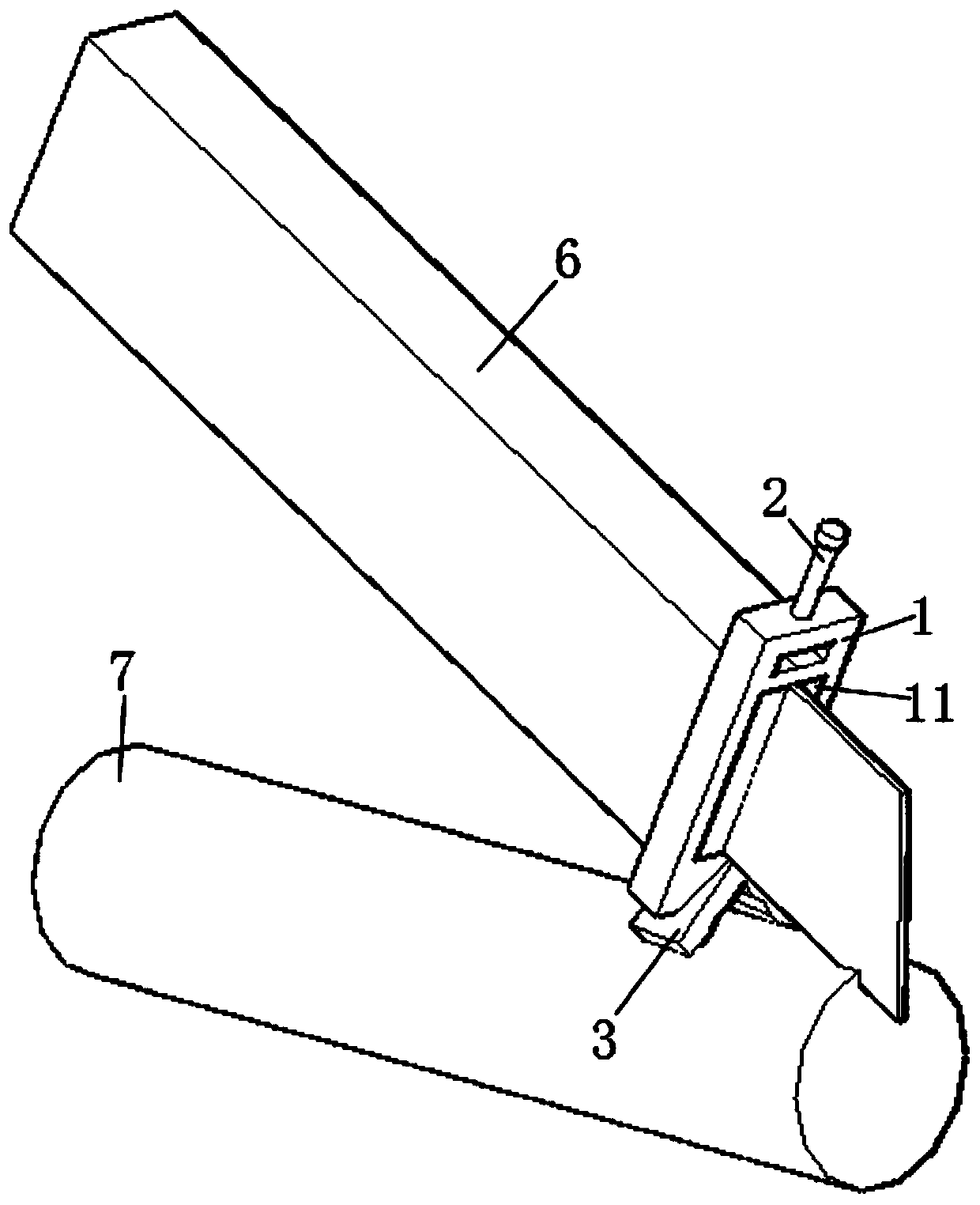
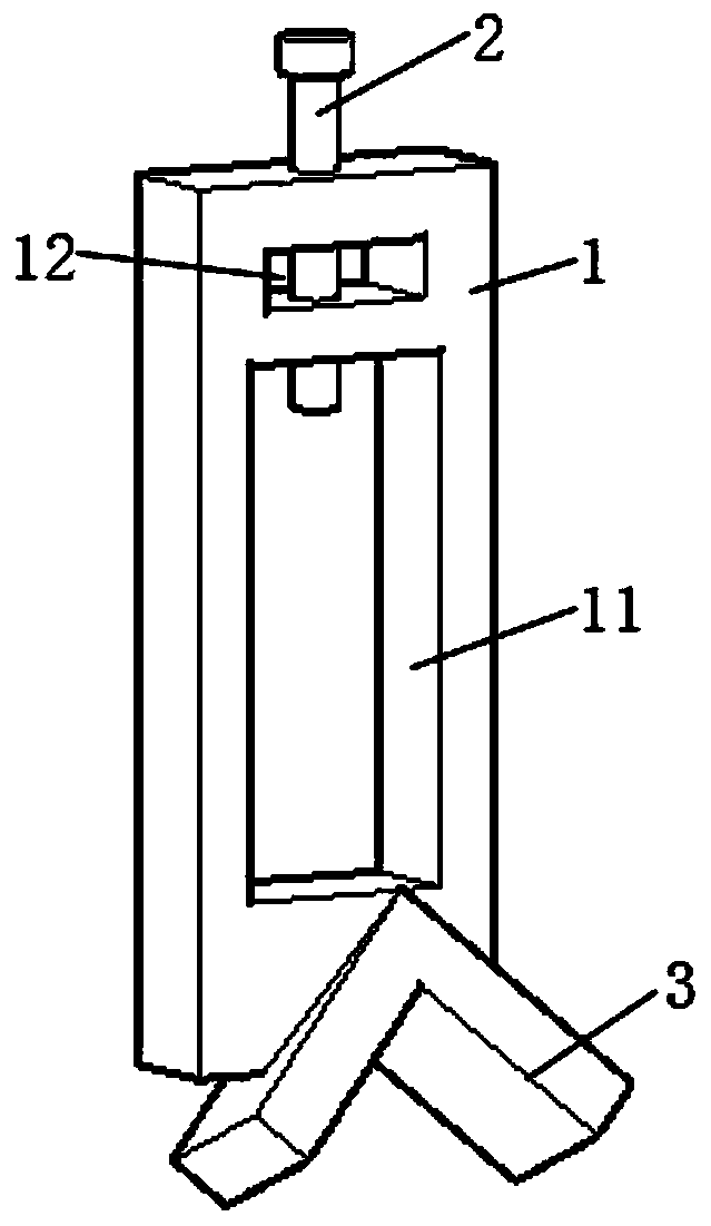
[0032] refer to figure 1 and figure 2 , the present embodiment discloses the anti-deviation device for cutting cables, including the anti-deviation device body 1 , the tool locking bolt 2 , and the triangular card 3 . The main body 1 of the anti-deviation device is obliquely fixed on the top of the triangular card 3, and the two are integrally formed. The body 1 of the anti-deviation device is provided with a through cutter groove 11 along the length direction of the cable 7 . The clamping slot opening of the triangular card 3 is set downwards, and is vertically stuck on the top of the horizontally placed cable 7 . The cutter 6 is inserted into the through cutter groove 11 , and the cutting end abuts against the top surface of the cable 7 . The tool locking bolt 2 passes through the threaded hole on the body 1 of the anti-deviation device 1 , and penetrates into the tool slot 11 , and the bottom end abuts against the top handle of the tool 6 .
[0033] First cutter 6 is i...
Embodiment 2
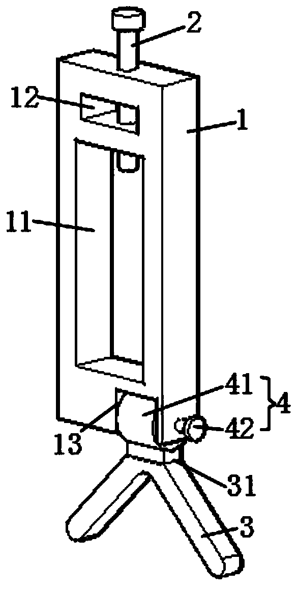
[0040] refer to image 3 and Figure 4 The difference between the second embodiment and the first embodiment is that the side of the bottom of the anti-deviation device body 1 deviated from the vertical center line is provided with a first installation groove 13 opening downward. A first rotating cylinder 41 whose axis direction is consistent with the width direction of the anti-deviation device body 1 is arranged in the first installation groove 13 . A shaft 43 fixed by bolts passes through the axis of the first drum 41 . Both ends of the rotating shaft 43 pass through the main body 1 of the anti-deviation device 1 respectively. And one end of the rotating shaft 43 is fixedly welded with a first adjusting knob 42 , and the other end is threaded with a detachable first locking nut 44 . The triangular card 3 is fixed on the first drum 41 through the connecting block 31 .
[0041] Insert the cutter 6 into the cutter groove 11, then rotate the cutter lock bolt 2 to hold again...
Embodiment 3
[0043] refer to Figure 5 and Figure 6 The difference from the first and second embodiments is that the bottom of the anti-deviation device body 1 is provided with a second installation groove 14 that is open on three sides. A second drum 51 that moves along the width direction of the anti-deviation device body 1 is installed in the second installation groove 14 . The second drum 51 is sleeved on the threaded rod 52 through thread fit. Both ends of the threaded rod 52 pass through the anti-deviation device body 1 respectively. And one end of the screw rod 52 is fixedly welded with a second adjusting knob 55 , and the other end is threadedly fitted with a second locking nut 53 . The top of the second rotating drum 51 is slidably connected in a limiting sliding slot (not shown) provided on the top of the second installation slot 14 through a limiting slider 54 .
[0044] An arc-shaped sliding slot 81 is opened on the body of the second drum 51 . An arc-shaped slider (not s...
PUM
 Abstract
Description
Claims
Application Information