Unlock instant, AI-driven research and patent intelligence for your innovation.

LRA driving pulse waveform design method based on Kaiser window

A driving pulse and waveform technology, applied in the field of electronics, can solve the problems of driving pulse signal jitter, fundamental frequency signal phase error, etc., and achieve the effect of improving interference, efficiency and response speed optimization

Active Publication Date: 2020-06-16
SHANGHAI FOURSEMI SEMICON CO LTD
View PDF6 Cites 4 Cited by
  • Summary
  • Abstract
  • Description
  • Claims
  • Application Information

AI Technical Summary

Problems solved by technology

[0011] 5. When the F0 tracking function of the LRA is turned on, the delay of each driving pulse depends on the BEMF zero-crossing position of the previous cycle. Due to the noise of the BEMF detection circuit and the random changes in the external environment of the LRA, the driving pulse signal will also jitter
Due to the asymmetry of the pulse, the high-frequency component of the square wave after the first-order IIR filter will cause an additional phase error of the fundamental frequency signal at the zero-crossing point

Method used


Image

  • LRA driving pulse waveform design method based on Kaiser window
  • LRA driving pulse waveform design method based on Kaiser window
  • LRA driving pulse waveform design method based on Kaiser window

Examples


Embodiment Construction

[0050] In order to make the purpose, technical solution and advantages of the present application clearer, the technical solution of the present application will be clearly and completely described below in conjunction with specific embodiments of the present application and corresponding drawings. Apparently, the described embodiments are only some of the embodiments of the present application, rather than all the embodiments. Based on the embodiments in this application, all other embodiments obtained by persons of ordinary skill in the art without making creative efforts belong to the scope of protection of this application.

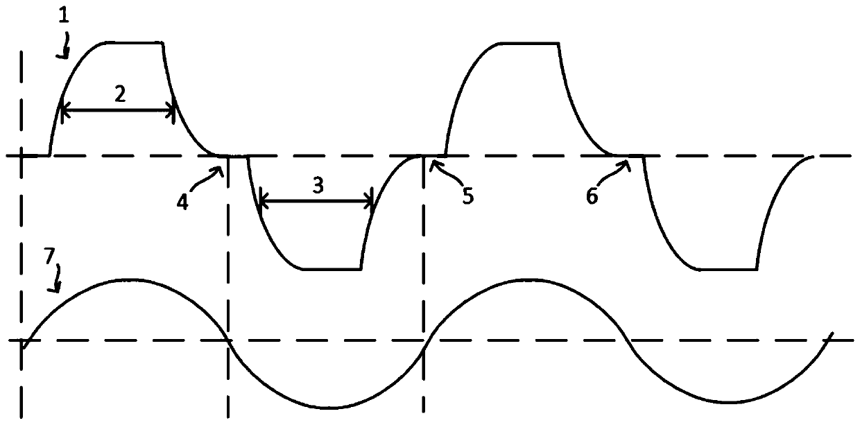
[0051] LRA driving signal model

[0052] The Kaiser window is defined as follows:

[0053]

[0054] Where α=M / 2, M is the window length, I 0 (·) is the zero-order modified Bessel function of the first kind. β is the modulation coefficient used for the Bessel function, which can be used to adjust the main lobe width and side lobe suppression of t...


PUM


Abstract

The invention discloses an LRA driving pulse waveform design method and device based on a Kaiser window. The method has the advantages that high-frequency noise caused by zero-crossing jitter of the driving pulse signal and higher harmonics of the pulse signal can be effectively suppressed, so that the interference to an audio system of handheld equipment is improved. The method can be used for truncating any non-causal and infinite ideal pulse response, and meets the half-cycle limitation requirement of the LRA driving pulse signal width. The method has symmetry and meets the impulse responserequirement of a linear phase system, so that the fundamental frequency phase corresponding to the zero crossing point of the LRA driving signal is not influenced by higher harmonics. An adjustable parameter [beta] is provided, so that compromise between the main lobe width and the sidelobe attenuation is facilitated. According to different requirements of different application occasions (LRA long vibration or short vibration), the noise, the efficiency and the response speed can be optimized by adjusting the beta.

Description

technical field [0001] The present application relates to the field of electronic technology, in particular to a method for designing an LRA driving pulse waveform. Background technique [0002] The linear resonant motor (LRA) driver chip usually obtains the acceleration and phase information of the LRA vibrator by detecting the back electromotive force (BEMF) at the zero crossing point of the driving signal, so as to control the frequency and amplitude of the driving signal through feedback to achieve fast and accurate vibration feedback effect. The existing driving pulse waveform diagram is as follows figure 1 shown. [0003] figure 1 Among them, 1 is the output signal waveform of the LRA driver chip, 2 is the forward driving pulse signal of the LRA driver chip, 3 is the reverse driving pulse signal of the LRA driver chip, 4, 5, 6 are the zero crossing points of the driving signal, and 7 is the LRA The BEMF waveform of the vibrator. [0004] Its working principle is t...

Claims


Application Information

Patent Timeline
Patent Type & Authority Applications(China)
IPC IPC(8): H03K3/017H02P23/04H02P23/14H02P25/032H02P25/06
CPCH03K3/017H02P23/14H02P23/04H02P25/032H02P25/06Y02D30/70
Inventor 石宏霄
Owner SHANGHAI FOURSEMI SEMICON CO LTD