A kind of feed pretreatment equipment
A pretreatment and feed technology, applied in the direction of feed, grain processing, food science, etc., can solve the problems of increased transshipment time, waste of power, large dust, etc., and achieve the effect of increasing the crushing time
- Summary
- Abstract
- Description
- Claims
- Application Information
AI Technical Summary
Problems solved by technology
Method used
Image
Examples
specific Embodiment approach 1
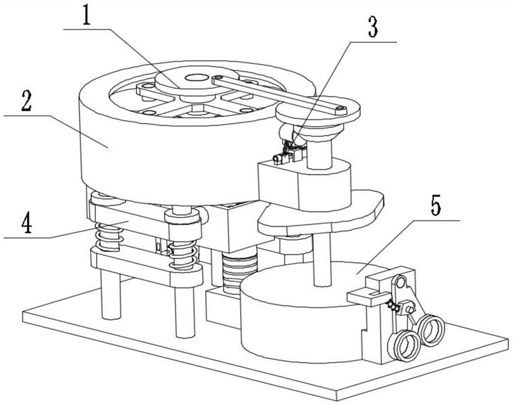
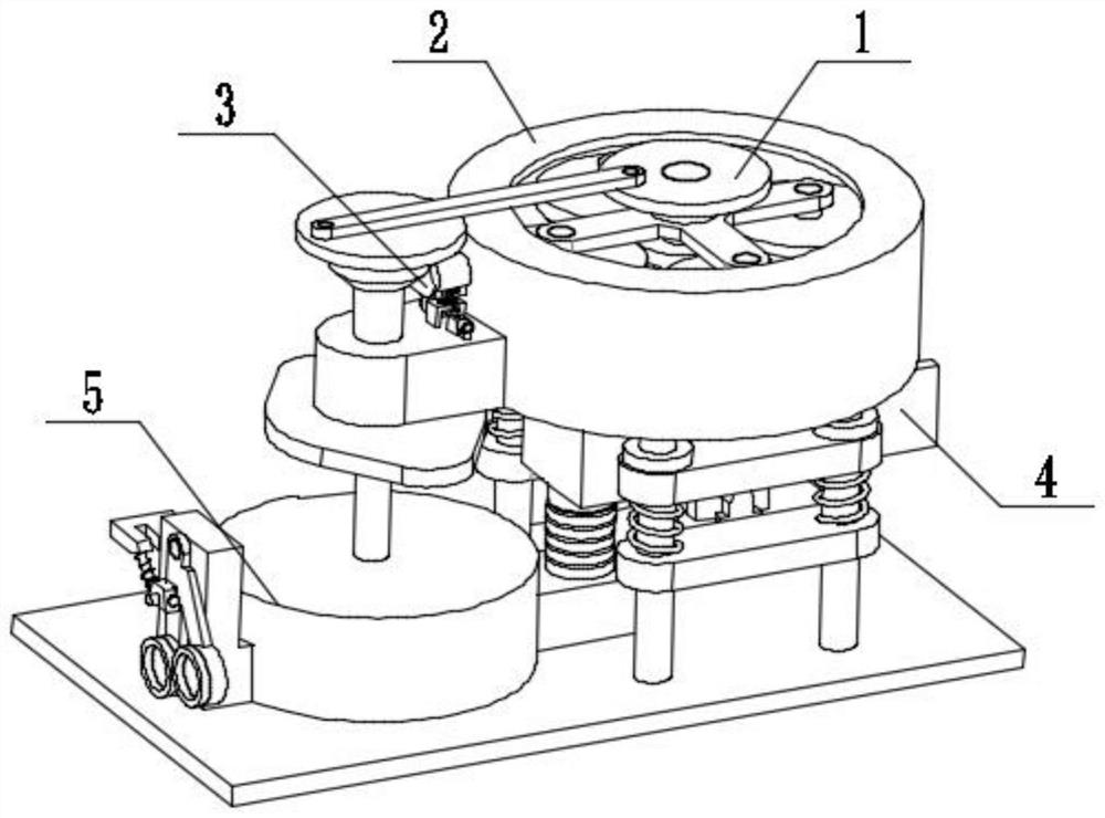
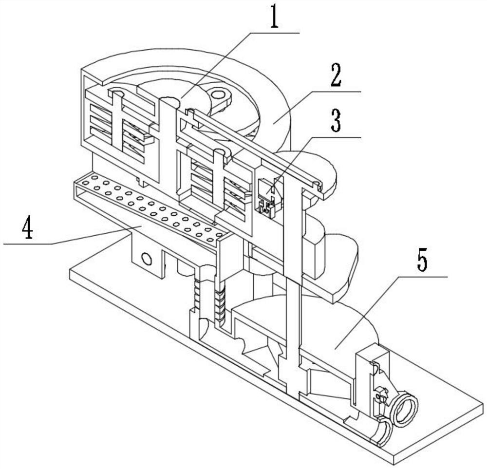
[0034] Combine below figure 1 , figure 2 , image 3 , Figure 4 , Figure 5 , Figure 6 , Figure 7 , Figure 8 , Figure 9 , Figure 10 , Figure 11 , Figure 12 , Figure 13 , Figure 14 , Figure 15 , Figure 16 , Figure 17 To illustrate this embodiment, the present invention relates to a feed processing equipment, more specifically a feed pretreatment equipment, including a crushing mechanism 1, a crushing cavity mechanism 2, a safety drive mechanism 3, a screening mechanism 4, and a collection box Mechanism 5, the equipment can be crushed, the equipment can control the rhythm of crushing and discharging to increase the crushing time, the equipment can be produced safely, the equipment can be screened, and the equipment can recover miscellaneous materials while producing dust-free.
[0035] The crushing mechanism 1 is connected with the crushing chamber mechanism 2, the crushing chamber mechanism 2 is connected with the safety driving mechanism 3, the safe...
specific Embodiment approach 2
[0037] Combine below figure 1 , figure 2 , image 3 , Figure 4 , Figure 5 , Figure 6 , Figure 7 , Figure 8 , Figure 9 , Figure 10 , Figure 11 , Figure 12 , Figure 13 , Figure 14 , Figure 15 , Figure 16 , Figure 17 Describe this embodiment, this embodiment will further explain the first embodiment, the crushing mechanism 1 includes a crushing wheel 1-1, a gear 1-2, a rotating shaft 1-3, a rotating arm 1-4, and a connecting plate 1 -5, bearing block 1-6, articulated arm 1-7, rotating disc 1-8, bevel gear 1-9, rotating shaft I1-10, cam 1-11, impeller 1-12, crushing wheel 1-1 and The rotating shaft 1-3 is connected, the connection mode of the rotating shaft 1-3 and the rotating arm 1-4 is a bearing connection, the gear 1-2 is connected with the rotating shaft 1-3, and the rotating arm 1-4 is connected with the connection plate 1-5, The bearing seat 1-6 is arranged on the connecting plate 1-5, the connecting plate 1-5 is hinged with the hinged arm 1-7...
specific Embodiment approach 3
[0039] Combine below figure 1 , figure 2 , image 3 , Figure 4 , Figure 5 , Figure 6 , Figure 7 , Figure 8 , Figure 9 , Figure 10 , Figure 11 , Figure 12 , Figure 13 , Figure 14 , Figure 15 , Figure 16 , Figure 17 Describe this embodiment, this embodiment will further explain the first embodiment, the crushing chamber mechanism 2 includes a geared vertical shaft 2-1, a casing 2-2, a leg 2-3, a limit plate 2-4, a vibration Spring 2-5, intermediate support 2-6, base 2-7, bearing seat I2-8, sliding gate mechanism 2-9, support 2-10, matching groove 2-11, outlet 2-12, light hole 2- 13. The connection mode between the geared vertical shaft 2-1 and the bearing seat 1-6 is bearing connection, the geared vertical shaft 2-1 is connected with the casing 2-2, the casing 2-2 is connected with the leg 2-3, and the leg 2- 3 is connected with the limit plate 2-4, the outrigger 2-3 is connected with the middle support 2-6, the vibration spring 2-5 is set on the o...
PUM
 Abstract
Description
Claims
Application Information
 - R&D
- Intellectual Property
- Life Sciences
- Materials
- Tech Scout
- Unparalleled Data Quality
- Higher Quality Content
- 60% Fewer Hallucinations
Browse by: Latest US Patents, China's latest patents, Technical Efficacy Thesaurus, Application Domain, Technology Topic, Popular Technical Reports.
© 2025 PatSnap. All rights reserved.Legal|Privacy policy|Modern Slavery Act Transparency Statement|Sitemap|About US| Contact US: help@patsnap.com


