
Metal powder grinding device

A grinding device and metal powder technology, which is applied in the field of metal processing, can solve the problems of insufficient crushing and grinding, high equipment cost, etc., and achieve the effect of enhancing the crushing effect, improving the effect, and reducing the size of raw materials

Inactive Publication Date: 2021-06-04
李素侠
View PDF0 Cites 0 Cited by
  • Summary
  • Abstract
  • Description
  • Claims
  • Application Information

AI Technical Summary

Problems solved by technology

The crushing and grinding of metal by the metal processing device in the prior art is not sufficient, and two driving sources are used for crushing and grinding at the same time, and the equipment cost is relatively high. Therefore, the present invention proposes a metal powder grinding device that can solve the above problems

Method used


Image

  • Metal powder grinding device
  • Metal powder grinding device
  • Metal powder grinding device

Examples


Embodiment 1

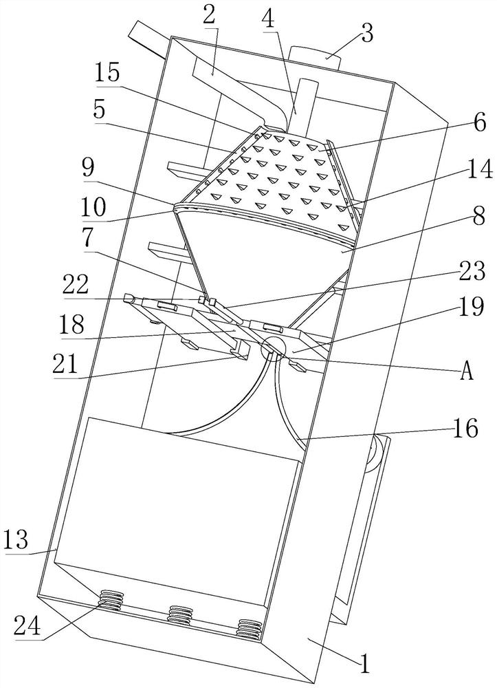
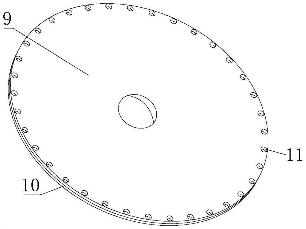
[0029] A metal powder grinding device includes a box body 1, a pulverizing device and a grinding device, the pulverizing device includes a pulverizing shell 5, the pulverizing shell 5 is fixedly installed above the box body 1, and a rotating block 6 is arranged in the pulverizing shell 5 , a plurality of second pulverizing teeth 15 are evenly distributed on the inner wall of the pulverizing shell 5, and a plurality of first pulverizing teeth 14 are evenly distributed on the side of the rotating block 6; the grinding device includes a grinding shell 7, and the grinding shell 7 is fixedly installed on the In the box 1, the grinding shell 7 is located below the pulverizing shell 5. The grinding shell 7 is provided with a grinding block 8, and a rotating device is arranged between the rotating block 6 and the grinding block 8. The pulverizing shell 5 and the grinding shell There is a feeding device between 7.

[0030] Further, the rotating device includes a first motor 3. The firs...

Embodiment 2

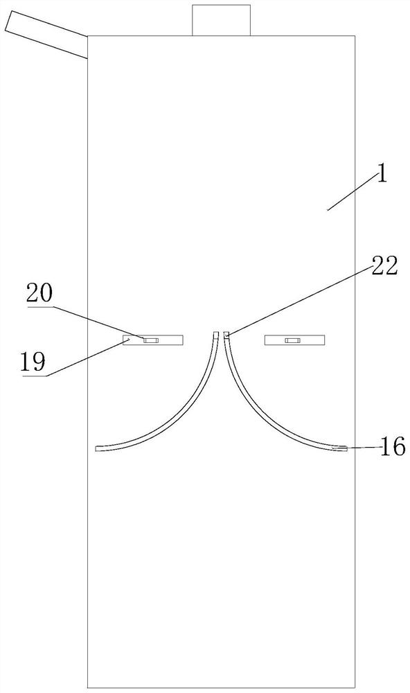
[0036] As an optional situation, the discharging device includes two discharging plates 18. The front and rear sides of the two discharging plates 18 are respectively connected to the inner walls of the left and right sides of the box body 1 through movable shafts. The top of the 18 is in contact with the bottom of the grinding shell 7 , the two discharge plates 18 are provided with a discharge plate driving device at the ends close to each other, and the bottom of the two discharge plates 18 is provided with a support device.

[0037]Further, the driving device of the discharge plate includes four connecting rods 23, and the four connecting rods 23 are fixedly installed on the ends of the two discharge plates 18, which are close to each other. A quarter arc-shaped through-slot 16, four connecting rods 23 are fixedly connected to a slider 22 on the side away from the discharge plate 18, and the slider 22 is slidably connected to the corresponding quarter-arc-shaped through-slot...

Embodiment 3

[0045] As an optional situation, the support device includes two backing plates 19, the two backing plates 19 are respectively located under the two discharge plates 18, and the two backing plates 19 are respectively against the bottoms of the two discharge plates 18, The front ends of the two backing plates 19 run through the front side of the box body 1, and four guide rails 21 are fixedly connected on the inner walls of the front side and the rear side of the box body 1, and the four guide rails 21 are matched with the backing plate 19. The two backing plates 19 are plugged into the corresponding guide rails 21 respectively, and the guide rails 21 limit the positions of the two backing plates 19, so that the two backing plates 19 respectively support the bottoms of the two discharge plates 18 to prevent the two The two discharge plates 18 are separated, the rear ends of the two backing plates 19 run through the rear side of the box body 1, and a fixing device is provided bet...


PUM


Abstract

The invention discloses a metal powder grinding device which comprises a box body, a smashing device and a grinding device. The smashing device comprises a smashing shell, a plurality of second smashing teeth are evenly distributed on the inner wall of the smashing shell, a plurality of first smashing teeth are evenly distributed on the side face of a rotating block, and the grinding device comprises a grinding shell; and a rotating device is arranged between the rotating block and a grinding block, and a discharging device is arranged between the smashing shell and the grinding shell. When the metal powder grinding device is used, a first motor drives a first rotating shaft to rotate, the first rotating shaft drives the rotating block, the grinding block and a first discharging plate to rotate, and when the rotating block rotates, the first smashing teeth and the second smashing teeth smash raw materials in the smashing shell; and the smashed raw materials fall into the grinding shell through discharging holes in the first discharging plate and a second discharging plate to be ground, and the discharging holes in the first discharging plate and the second discharging plate are repeatedly separated and overlapped, so that the smashing time of the raw materials in the smashing shell is prolonged, and the crushed raw materials are more convenient to grind.

Description

technical field [0001] The invention relates to the technical field of metal processing, in particular to a metal powder grinding device. Background technique [0002] Metal materials are widely used in people's lives and production. During the processing of existing metals, they need to be crushed, ground, and sieved before they can be further extracted. Metal powders are loose substances, and their properties comprehensively reflect the metal itself. properties and properties of individual particle groups. Metal processing devices in the prior art are not sufficient for pulverizing and grinding metals, and two driving sources are used for pulverizing and grinding at the same time, resulting in high equipment cost. Therefore, the present invention proposes a metal powder grinding device that can solve the above problems. SUMMARY OF THE INVENTION [0003] The purpose of the present invention is to provide a metal powder grinding device to solve the above-mentioned problem...

Claims


Application Information

Patent Timeline
IPC IPC(8): B22F9/04B02C2/10B02C2/00B02C23/00B02C23/16
CPCB02C2/00B02C2/10B02C23/00B02C23/16B22F9/04
Inventor 李素侠
Owner 李素侠
Learn More