Variable-feed cutting method for circular groove machining

A cutting method and annular groove technology, which are applied in the field of mechanical processing, can solve the problems of poor chip breaking effect, etc., and achieve the effects of improving tool life and processing efficiency, good curling effect, and stable roughness

Active Publication Date: 2020-06-19
浙江海德曼智能装备股份有限公司
View PDF6 Cites 1 Cited by
  • Summary
  • Abstract
  • Description
  • Claims
  • Application Information

AI Technical Summary

Problems solved by technology

[0005] The purpose of the present invention is to solve the above-mentioned problems in the existing technology, and propose a variable feed cutting method for annular groove processing. The present invention solves the problem of poor chip breaking effect in the existing groove processing

Method used


Image

  • Variable-feed cutting method for circular groove machining

Examples


Embodiment 1

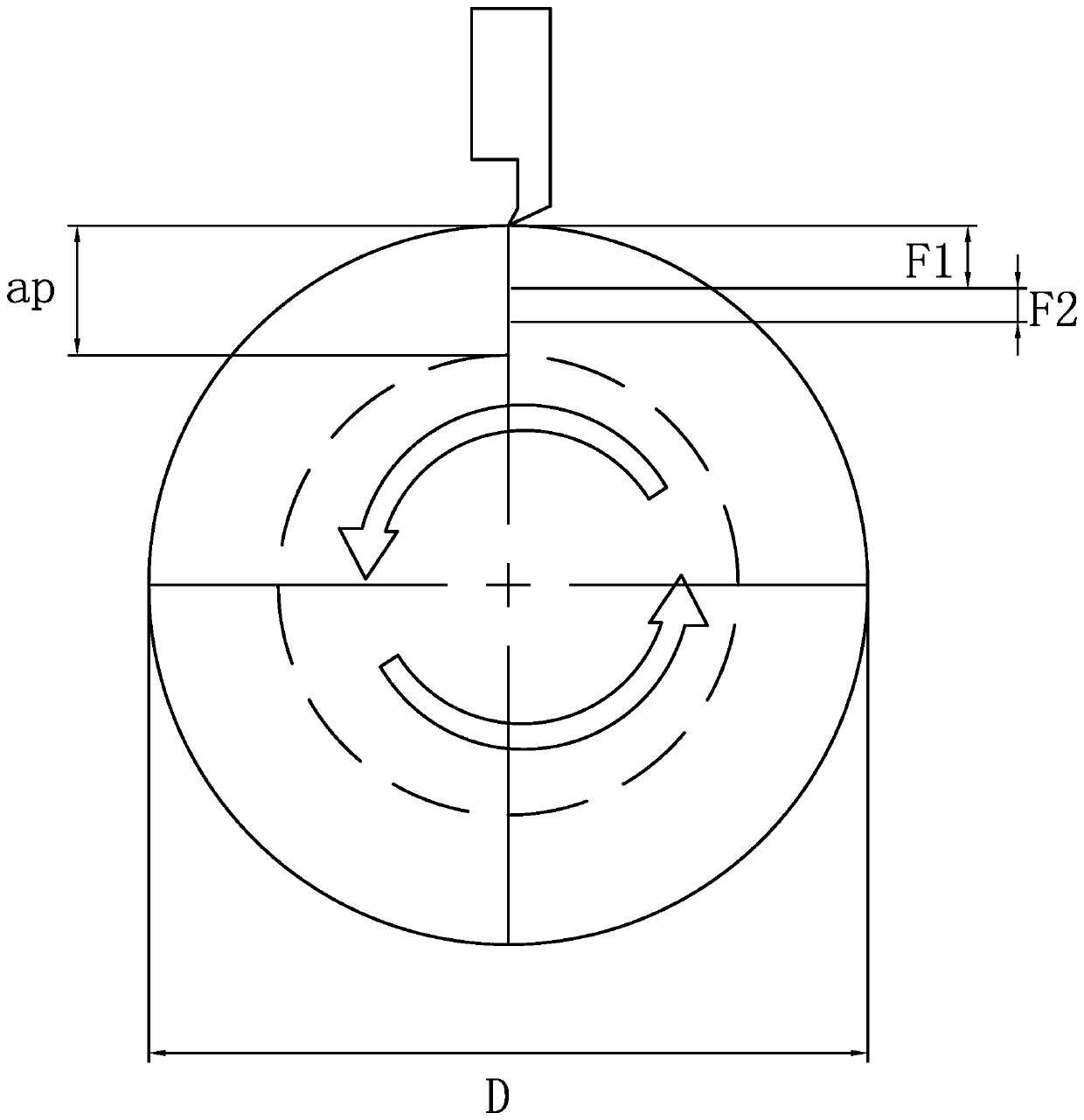
[0023] Specifically, in this embodiment, this method is applied to a CNC lathe. The CNC lathe performs grooving on the workpiece by executing multiple variable feed cycles in the same cutting circle. Each variable feed cycle includes normal feed Quantity F1 and variable feed F2, before processing, set the diameter of the cutting circle D, set the expansion rate of the material β, set the depth of cut ap per revolution of the spindle, and set the required length of chips cut out by a variable feed cycle L, set the normal feed amount F1, and then calculate the F2=(L*ap-β*F1*лD) / (лD*β) through the formula to set, where as figure 1 As shown, F2, F1, and ap need to satisfy the following relationship: F2

[0024] Step 1, the workpiece is cut with the feed rate of F1, and the number of rotations of the spindle at this time is F1 / ap;

[0025] Step 2: After step 1 is completed, the workpiece is cut with the feed rate of F2. At thi...

Embodiment 2

[0030] The technical solution of this embodiment is basically the same as the technical solution of the first embodiment, the difference is that in this embodiment, the variable feed rate is not calculated by a formula, but an empirical value obtained by an experimental test.


PUM


Abstract

The invention provides a variable-speed cutting method for circular groove machining, and belongs to the field of machining. By the adoption of the variable-speed cutting method for circular groove machining, the problem of poor chip breaking effect during grooving in the prior art is solved. According to the variable-speed cutting method for circular groove machining, an automatic machine tool executes multiple variable-speed cycles within one cutting circumference to conduct grooving on a workpiece, and each variable-feed cycle includes a normal feed F1 and a variable feed F2; before machining, the cutting depth ap is set, and F1 and F2 are set, wherein F2<F1<ap, and F1+F2<ap; and then the following steps are conducted: Step 1, the workpiece is cut according to the feed F1, wherein the number of rotating turns of a spindle is F1 / ap; Step 2, the workpiece is cut according to the feed F2, wherein the number of rotating turns of the spindle is F2 / ap; and after one variable-feed machining cycle formed by Step 1 and Step 2 is completed, actions in the variable-feed cycle are repeated cyclically until grooving within one cutting circumference is completed. In this way, a good chip tailcurling effect can be realized.

Description

technical field [0001] The invention belongs to the field of machining, and relates to a variable feed cutting method for machining annular grooves. Background technique [0002] At present, in the grooving processing of large disc-shaped and cylindrical rotary rests by CNC turning, for example, in the field of gear processing, in the grooving processing of the outer diameter annular groove of the gear protruding from the cylinder, the workpiece material is mainly stainless steel. For metal materials such as high-quality carbon steel and alloy steel, for automatic processing machine tools such as CNC machine tools, the continuous chips generated by metal materials will cause blockage during the cutting process, thereby hindering the automatic processing of the machine tool system. [0003] Specifically, in the process of turning and grooving, when the groove is wider and deeper, the cutting amount is large, and the obtained iron filings are longer without loss of efficiency,...

Claims


Application Information

Patent Timeline
Patent Type & Authority Applications(China)
IPC IPC(8): B23B1/00
CPCB23B1/00B23B2220/126
Inventor 汪助高兆春刘丽
Owner 浙江海德曼智能装备股份有限公司
Why Eureka
Try Eureka