Four-pressure-roller mechanical intra-machine puller

A mechanical puller technology, applied in the field of metal cutting, can solve the problems of limited adjustment range, short overall life, large investment, etc., and achieve the effect of expanding the specification range, reliable pulling process, and reducing wear

Active Publication Date: 2020-06-19
HUBEI JIANGSHAN HEAVY IND
View PDF6 Cites 1 Cited by
  • Summary
  • Abstract
  • Description
  • Claims
  • Application Information

AI Technical Summary

Problems solved by technology

The existing mechanical puller in the machine has a small number of claws, which belong to point contact, easy to loosen, and the adjustment range is limited. During the pulling process, the axial force is hard to pull out and inserted, which is easy to be damaged and the overall life is short.
A longer chuck must be left, otherwise the puller cannot be used
However, the automatic feeding device outside the machine and industrial robots require a large investment, high cost, long cycle, and large floor space. It is not economical to process small and medium batches of workpieces.

Method used


Image

  • Four-pressure-roller mechanical intra-machine puller
  • Four-pressure-roller mechanical intra-machine puller
  • Four-pressure-roller mechanical intra-machine puller

Examples


Embodiment Construction

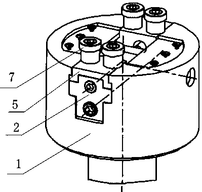
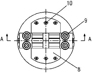
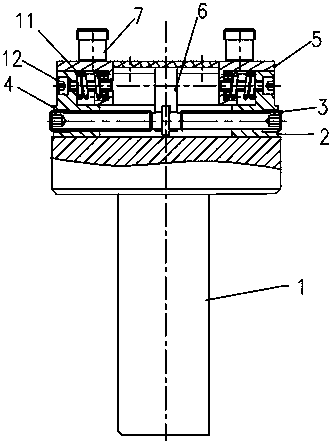
[0021] figure 1 , 2 , 3,4,5, right fixed block 2, left fixed block 4, stage clip 11, slide block 5 are connected by countersunk head hexagonal long screw 12 to form a single sliding body. The left and right sliding bodies are connected by a two-way screw 3, and the two-way screw 3 cooperates with the fixed bushing 6, and they jointly form a sliding assembly pair. There is a flat platform on the small end of the body 1, which is installed in the tool holder of the CNC lathe through a standard interface. The fixed axle sleeve 6 is fixed in the middle-shaped chute of the body 1 by the fastening screw 13, and is fixed. A pair of pressure rollers 7 are installed on the end face of the slide block 5 by means of countersunk head hexagonal short screws 9 . Rotate the two-way screw 3, the two sliding bodies slide relatively in the groove, and the pressing wheel 7 moves synchronously thereupon, thereby realizing the adjustment of the clamping range of the puller. On the end face of ...


PUM


Abstract

The invention discloses a four-pressure-roller mechanical intra-machine puller. A main body is of a stepped structure composed of a large cylinder and a small cylinder, a sliding groove penetrating ina radial direction is formed in the middle of the upper end face of the large cylinder, a reverse-flighted screw is installed in the sliding groove, a fixed sleeve is installed at a middle flange ofthe reverse-flighted screw, both ends of the reverse-flighted screw are inserted at threaded holes of two sliding bodies, the sliding bodies are installed opposite to each other, the upper end faces of the two sliding bodies are respectively equipped with two pressure rollers for pressing a to-be-pulled workpiece, the pressure rollers protrude out of an opening of the upper surface of the slidinggroove, each sliding body comprises a fixing block and a sliding block, the sliding blocks are slidably connected with the fixing blocks through long screws, compression springs sleeve rod portions ofthe long screws, one ends of the compression springs abuts against the sliding blocks, and the other ends of the compression springs abut against the fixing blocks. According to the puller, rough andfine adjustment of clamping force can be carried out, the degree of abrasion of a clamping jaw of the puller is reduced, replacement of the pressure rollers is extremely convenient and economical, and the overall service life of the puller is prolonged.

Description

technical field [0001] The invention belongs to the field of metal cutting processing, and in particular relates to an automatic material pulling mechanism for CNC lathe processing, which is convenient for continuous turning processing of small and medium-sized composite materials without human intervention. Background technique [0002] At present, when CNC lathes are processing small and medium batches of small and medium-sized parts, if there is no automatic pulling mechanism and the program running time is short, the operator will be bound to a single machine position, loading and unloading workpieces continuously, and it is impossible to carry out one-person double-machine operation , and the action of the worker is single, and the labor intensity is high. The automatic puller can realize the long-term automatic and unmanned continuous operation of the CNC lathe. The existing mechanical puller in the machine has a small number of claws, which are point contacts, easy t...

Claims


Application Information

Patent Timeline
Patent Type & Authority Applications(China)
IPC IPC(8): B23B31/103B23B15/00
CPCB23B31/103B23Q7/00
Inventor 周德民方振红谢家松刘葵居大伟
Owner HUBEI JIANGSHAN HEAVY IND
Why Eureka
Try Eureka