
A Workpiece Clamping and Turning Mechanism for Machining

A technology of mechanical processing and turning mechanism, which is applied in the direction of workpiece clamping device, workbench, manufacturing tools, etc., can solve the problems of insufficient accuracy of firm turning, imperfect workpiece clamping and turning, and low work efficiency, etc. Achieve the effects of improved flipping position and flipping accuracy, strong firmness, and improved clamping firmness

Active Publication Date: 2021-10-08
临沂市铸信机械有限公司
View PDF0 Cites 0 Cited by
  • Summary
  • Abstract
  • Description
  • Claims
  • Application Information

AI Technical Summary

Problems solved by technology

[0003] However, in the current machining process in the market, after the workpiece is clamped and processed, most of the flipping of the workpiece is to loosen the clamping mechanism, and then clamp it again after flipping. There are also two mechanisms for flipping and clamping for auxiliary operations. This not only increases the difficulty of operation, but also reduces the work efficiency. There is also a clamping and turning integrated equipment, but this equipment is not perfect for the clamping and turning of the workpiece, and the firmness of its clamping and the accuracy of turning are not high enough, especially When aiming at irregular workpieces, during the clamping and turning process, due to insufficient clamping, shaking and friction may easily cause damage to the surface of the workpiece. Therefore, those skilled in the art provide a workpiece clamping and turning mechanism for machining , to solve the problems raised in the above background technology

Method used


Image

  • A Workpiece Clamping and Turning Mechanism for Machining
  • A Workpiece Clamping and Turning Mechanism for Machining
  • A Workpiece Clamping and Turning Mechanism for Machining

Examples


Embodiment Construction

[0020] The following will clearly and completely describe the technical solutions in the embodiments of the present invention with reference to the accompanying drawings in the embodiments of the present invention. Obviously, the described embodiments are only some, not all, embodiments of the present invention. Based on the embodiments of the present invention, all other embodiments obtained by persons of ordinary skill in the art without making creative efforts belong to the protection scope of the present invention.

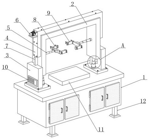
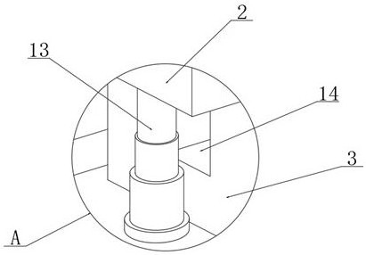
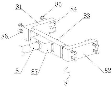
[0021] see Figure 1~5 , in an embodiment of the present invention, a workpiece clamping and turning mechanism for mechanical processing includes a chassis 1, a workbench 11 is placed in the middle of the upper end of the chassis 1, and the upper end of the chassis 1 is located on both sides of the workbench 11 and correspondingly installed Two vertical plates 3, the inner side of the vertical plate 3 is connected with the gantry 2, the inner side of the verti...


PUM


Abstract

The invention discloses a workpiece clamping and turning mechanism for mechanical processing, relates to the technical field of mechanical processing, and comprises a machine case, a worktable is placed in the middle of the upper end of the machine case, and the upper end of the machine case is located on both sides of the workbench and correspondingly installed Two vertical plates, the inner surface of the vertical plate is connected with a gantry, the inner surface of the vertical plate is located at the bottom end of the gantry, and a hydraulic cylinder is arranged, and the outer side of the gantry is installed with a transmission casing, In addition, a first clamping mechanism is provided on the inner side of the gantry corresponding to one end of the conveyor casing, and a second clamping mechanism is installed on the inner side of the gantry corresponding to the other end of the conveyor casing. The clamping mechanism of the present invention can be adjusted up and down, and the two clamping mechanisms can be turned over synchronously, and the distance between the clamping mechanisms is adjustable, which is convenient for clamping workpieces of different sizes and irregularities, and is easy to operate and strong in firmness , so that both the flipping position and the flipping accuracy are improved.

Description

technical field [0001] The invention relates to the technical field of machining, in particular to a workpiece clamping and turning mechanism for machining. Background technique [0002] With the continuous improvement of the intelligence level of my country's manufacturing industry, based on the needs of lean production and cost control, automated production transmission lines have been widely used in the manufacturing industry. Under the background of the rapid improvement of automation and intelligence, the workpiece attitude changing mechanism with small footprint, compact mechanism, reliable use, high work efficiency and high degree of automation is an important indicator of the advanced status of the automatic production transmission line. [0003] However, in the current machining process in the market, after the workpiece is clamped and processed, most of the flipping of the workpiece is to loosen the clamping mechanism, and then clamp it again after flipping. There a...

Claims


Application Information

Patent Timeline
Patent Type & Authority Patents(China)
IPC IPC(8): B25B11/00B25H1/10
CPCB25B11/00B25H1/10
Inventor 江丽平
Owner 临沂市铸信机械有限公司
Learn More