A kind of 3d printer feeding assembly

A 3D printer and 3D printing technology, applied in the field of 3D printing, can solve problems such as material leakage

Active Publication Date: 2022-03-11
JIANGSU OURING THREE DIMENSIONAL SCI & TECH CO LTD
View PDF0 Cites 0 Cited by
  • Summary
  • Abstract
  • Description
  • Claims
  • Application Information

AI Technical Summary

Problems solved by technology

[0004] Therefore, the technical problem to be solved by the present invention is to overcome the defect in the prior art that the retraction of the wire feeder during the printing process can cause the tray to reverse at a certain angle, and even cause the material in the tray to pop out of the tray, thereby providing A kind of 3D printer feeding assembly

Method used


Image

  • A kind of 3d printer feeding assembly
  • A kind of 3d printer feeding assembly

Examples


Embodiment Construction

[0025] In order to make the object, technical solution and advantages of the present invention clearer, the present invention will be further described in detail below in conjunction with the accompanying drawings and embodiments. It should be understood that the specific embodiments described here are only used to explain the present invention, not to limit the present invention.

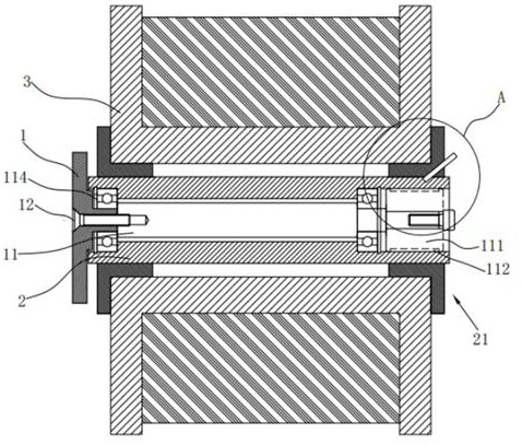
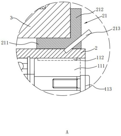
[0026] see figure 1 , the object of the present invention is to provide a 3D printer feeding assembly, which is used to install a 3D printing tray 3, which includes a material hanging bracket 1 at one end and a rotating shaft 11 that rotates synchronously with the material hanging bracket 1. The outer circumference of the shaft 11 is provided with a material hanging shaft 2, where the material tray 3 is sleeved on the outer circumference of the material hanging axis 2, and a support sleeve 21 is also provided between the material hanging shaft 2 and the material tray 3, and the support sleeve 21 is...


PUM


Abstract

The present invention relates to the technical field of 3D printing, in particular to a 3D printer feeding assembly, aiming to solve the problem that the retraction of the wire feeder in the printing process in the prior art can cause the material tray to reverse at a certain angle, and even cause the The technical point of the problem of the material coming out of the material tray is that it includes a material hanging bracket and a rotating shaft that rotates synchronously with the material hanging bracket. The outer periphery of the material hanging shaft is provided with a support sleeve that abuts against the side wall of the central axis hole of the material tray, and the material hanging shaft is relatively rotatable with the rotating shaft. Through the setting of the support sleeve, there is friction between the material hanging shaft and the material tray. When the material hanging shaft rotates, the friction force provided by the support sleeve enables the material tray to rotate, thereby realizing the material discharging. Function.

Description

technical field [0001] The invention relates to the technical field of 3D printing, in particular to a 3D printer feeding assembly. Background technique [0002] 3D printing technology appeared in the mid-1990s and is actually the latest rapid prototyping device utilizing technologies such as light curing and paper lamination. The working principle of it is basically the same as that of ordinary printing. The printer is filled with "printing materials" such as liquid or powder. After being connected to the computer, the "printing materials" are superimposed layer by layer through computer control, and finally the blueprint on the computer is turned into a real object. This printing technology is called 3D printing technology; 3D printers are equipped with different "printing materials" such as metals, ceramics, plastics, sand, etc., which are real raw materials. "Layer by layer, the blueprint on the computer is finally turned into a real thing. In layman's terms, a 3D prin...

Claims


Application Information

Patent Timeline
Patent Type & Authority Patents(China)
IPC IPC(8): B29C64/321B33Y40/00
CPCB29C64/321B33Y40/00
Inventor 朱永书金志敏
Owner JIANGSU OURING THREE DIMENSIONAL SCI & TECH CO LTD
Why Eureka
Try Eureka