
Ink box

A technology of an ink cartridge and an engaging part, which is applied in directions such as printing, can solve the problems of the ink cartridge 10 being detached and the moment unbalanced.

Active Publication Date: 2020-06-19
ZHUHAI NINESTAR MANAGEMENT CO LTD
View PDF8 Cites 2 Cited by
  • Summary
  • Abstract
  • Description
  • Claims
  • Application Information

AI Technical Summary

Problems solved by technology

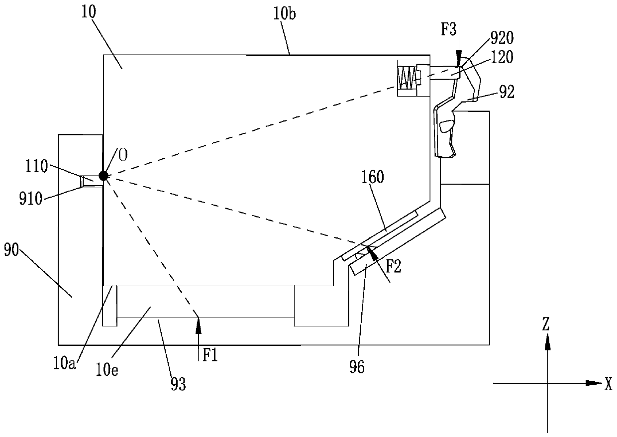
In this technical solution, after the ink cartridge 10 is installed on the mounting part 90, the ink cartridge 10 receives the force exerted on the chip 160 and the ink tube 93 by the contact pin part 96, and when the force exerted on the ink outlet 10e is large, the force exerted on the ink cartridge 10 by the rod hole 920 When F3 is not large enough, there will be a rotation trend with the position where the first clamping position 110 and the clamping groove 910 engage as the fulcrum O, and the force F1 received by the ink outlet 10e and the force F2 received by the chip 160 will appear. When the counterclockwise rotation moment formed relative to the rotation fulcrum O is greater than the clockwise rotation torque formed by the force F3 received by the second locking position 120 relative to the rotation fulcrum O, it is easy to cause the ink cartridge to move along the rotation fulcrum O due to moment imbalance. Rotation causes the ink cartridge 10 to detach from the mounting portion 90

Method used


Image

  • Ink box
  • Ink box
  • Ink box

Examples


Embodiment Construction

[0050] Terms used in the embodiments of the present application are only for the purpose of describing specific embodiments, and are not intended to limit the present application. The singular forms "a", "said" and "the" used in the embodiments of this application and the appended claims are also intended to include plural forms unless the context clearly indicates otherwise.

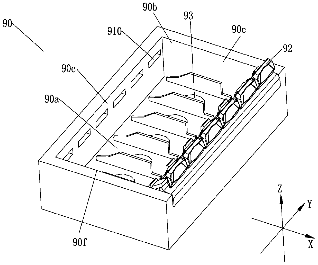
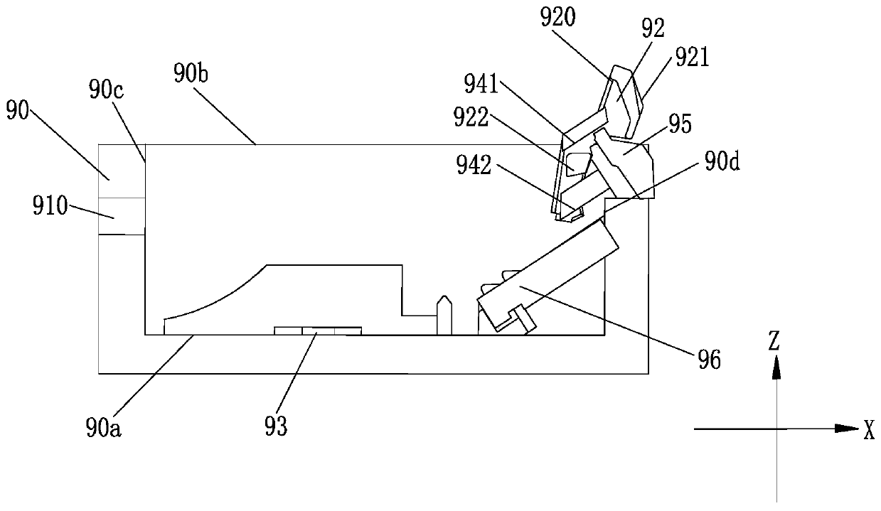
[0051] The application provides an ink cartridge for inkjet printing equipment, such as figure 1 with Image 6 As shown, the inkjet printing device includes a mounting part 90 and an ink cartridge 10 detachably mounted on the mounting part 90. For the detachably connected ink cartridge 10 and the mounting part 90, as figure 2 As shown, the installation part 90 is roughly in the shape of a cuboid and has an opening 90b, and the ink cartridge 10 can be installed into the installation part 90 from the opening 90b. Wherein, the installation part 90 has: a bottom surface 90a, an opening 90b, a first side ...


PUM


Abstract

The invention relates to the technical field of ink-jet printers, and particularly relates to an ink box. The ink box is detachably installed on an installation part and comprises a first clamping position and a second clamping position which are oppositely arranged on the two sides of the ink box, the first clamping position is matched with a clamping groove of the installation part, the ink boxfurther comprises a movable part, the second clamping position is connected to the movable part, the second clamping position comprises a first clamping part and a second clamping part, when the ink box is installed on the installation part, the movable part can move so that the first clamping part and the second clamping part can be connected with the installation part in a clamped mode at the same time. By means of the ink box, and the risk that the ink box is released due to excessive acting force when the ink box is installed on the installation part is avoided.

Description

technical field [0001] The present application relates to the technical field of inkjet printers, in particular to an ink cartridge. Background technique [0002] Inkjet printers are relatively commonly used printing and printing tools, especially in homes, shops, offices and other places. [0003] An inkjet printer has an ink cartridge and a mounting unit. The ink cartridge is detachably mounted on the mounting portion. At present, there are many ways to connect the ink cartridge for the inkjet printer to the mounting portion. Such as figure 1 Shown is a structural schematic diagram of an ink cartridge and an installation part in the prior art. The ink cartridge 10 has: a first card position 110, a second card position 120, a chip 160, and an ink outlet 10e. When the ink cartridge 10 is installed on the mounting part 90, the first locking position 110 on the ink cartridge 10 engages with the locking groove 910 on the mounting part, and the second locking position 120 e...

Claims


Application Information

Patent Timeline
IPC IPC(8): B41J2/175
CPCB41J2/17523B41J2/17553
Inventor 朱一静陈伟健
Owner ZHUHAI NINESTAR MANAGEMENT CO LTD
Learn More