An elevator car for carrying cars

A technology of elevator car and car, which is applied to elevators, elevators, transportation and packaging in buildings, etc. It can solve the problems of large force load, deformation of joints, and easy damage of inclined rods, etc., so as to avoid bending deformation , the effect of avoiding structural damage

Active Publication Date: 2021-04-02
CIVIL ELEVATOR
View PDF7 Cites 0 Cited by
  • Summary
  • Abstract
  • Description
  • Claims
  • Application Information

AI Technical Summary

Problems solved by technology

Yet this technical means still has defect, when automobile enters by car door, because the load of the front portion of car floor is extremely heavy, therefore the diagonal tie rod that connects car front portion (connects the pull-up rod of car frame front portion) The force load is also extremely large. After the car has completely entered the car body, the force load of the diagonal tie rods (upper tie rods) connecting the front and rear parts is basically balanced.
Due to the long-term large difference in force load of the diagonal tie rods (upper tie rods) connecting the front and rear parts, the diagonal stay rods (upper tie rods) connected to the front are prone to damage. Even the joints between the car frames are deformed, which affects the overall structural strength of the car frame.

Method used


Image

  • An elevator car for carrying cars
  • An elevator car for carrying cars
  • An elevator car for carrying cars

Examples


Embodiment example 1

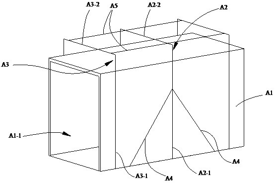
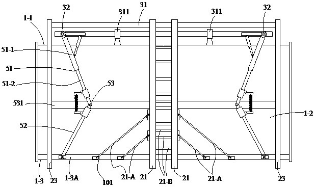
[0038] refer to figure 2 , an elevator car for carrying cars, including a car body, a main beam frame installed on the car body, and two auxiliary beam frames. The size of the car body is (2500mm-2800mm)*(6000mm-7000mm)*(2200mm -2500 mm). The car body is a single-door structure with a car door. In this implementation case, the direction in which the car door enters the car body is used as the front view direction, and the main beam frame and the two auxiliary beam frames are respectively installed on the In the middle, front and rear of the car, the main girder frame is fixed with two main vertical beams 21 on the two side panels 1-2 of the car. Since the height of the car is usually 2200mm-2500 mm, the main vertical beam The span of 21 is relatively large, so a plurality of reinforcing beams 21-B are fixedly connected between the two main vertical beams 21 of the same car side plate 1-2 to increase the structural strength. The two main vertical beams 21 and the car floor T...

Embodiment example 2

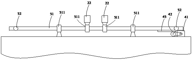
[0046] Embodiment 1 uses a cylinder and a telescopic rod to guide the rotation of the first connecting rod 51. In this embodiment, other solutions are adopted. Refer to Figure 9 , the end of the bracket 32 ​​is fixed with a mounting frame 32-A, and the mounting frame 32-A is fixed with a section of arc-shaped slide rail 73, and the arc-shaped slide rail 73 is formed by the hinge point of the first connecting rod at the support. At the center of the circle, the upper part of the first connecting rod is provided with a sliding piece 74 slidably fitted on the arc-shaped slide rail 73 .


PUM


Abstract

The invention discloses an elevator car for bearing an automobile. The elevator car for bearing the automobile comprises a car body of a single door structure, a main beam frame and two auxiliary beamframes, wherein the main beam frame and the two auxiliary beam frames are installed on the car body, at least one diagonal draw bar is connected between each main vertical beam of the main beam frameand the front part or the rear part of the corresponding side edge of a car bottom plate; an adjusting rod in the door direction is arranged above a car top plate, can move axially and is driven by apower mechanism, supports are connected to the portions, at the two sides of the main beam frame, of the adjusting rod, the two ends of the supports are provided with connecting mechanisms connectedto the front portions or the rear portions of the two side edges of the car bottom plate, the directions of applying acting force to the front portions and the rear portions of the side edges of the car bottom plate by the connecting mechanisms located on the different supports are different, and the direction and the magnitude of the acting force change along with the movement of the adjusting rod. The elevator car for bearing the automobile has the beneficial effects that on the premise of ensuring that the elevator car has enough integral structural strength, the technical aims of balancingthe stress load of the diagonal draw bars and avoiding excessive loss of the diagonal draw bars are achieved.

Description

technical field [0001] The invention relates to an elevator car, especially an elevator car for carrying automobiles. Background technique [0002] The structure of the elevator car carrying the car in the prior art is as follows: figure 1 As mentioned above, it consists of a car body A1, a main beam frame A2, and two auxiliary beam frames A3. The car body A1 is provided with a car door A1-1, which is a single-door car body. The main beam frame A2 is composed of two main vertical beams A2 -1 and the main beam A2-2 are connected, the main vertical beam A2-1 is fixed in the middle of the side plate of a box body, the main beam A2-2 is located on the top plate of the box body, and the two auxiliary beams A3 are located In the symmetrical position on the side, the auxiliary beam A3 is composed of two auxiliary vertical beams A3-1 and auxiliary beam A3-2, which are connected and fixed with the main beam frame A2 in the same way. Two connecting beams A5 are arranged on the roof ...

Claims


Application Information

Patent Timeline
Patent Type & Authority Patents(China)
IPC IPC(8): B66B11/02B66B5/00
CPCB66B5/0037B66B11/0226
Inventor 莫鋆杰沈怡萍高维
Owner CIVIL ELEVATOR
Why Eureka
Try Eureka