

Rolling device for low-temperature modified asphalt concrete construction
A modified asphalt and rolling device technology, which is applied to roads, road repairs, roads, etc., can solve the problems of non-adjustable rolling range and easy sticking of asphalt concrete to the rollers, and achieve convenient and fast switching, prevent sticking, Adaptable effect
- Summary
- Abstract
- Description
- Claims
- Application Information
AI Technical Summary
Problems solved by technology
Method used
Image

Examples
Embodiment 1
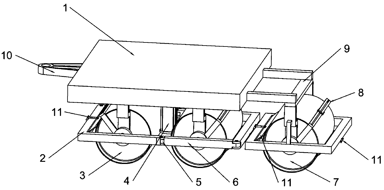
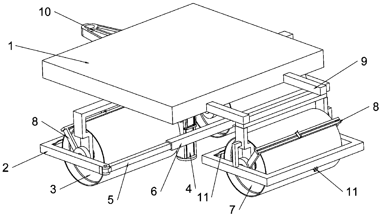
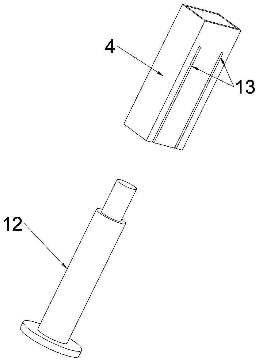
[0052] Embodiment 1, the present invention is a rolling device for low-temperature modified asphalt concrete construction, including an equipment base 1, characterized in that the equipment base 1 is hollow inside, and a hydraulic cylinder is fixedly connected to the lower end surface of the equipment base 1 12. A square casing 4 is sheathed on the outside of the hydraulic cylinder 12, and the square casing 4 is fixedly connected to the bottom surface of the hydraulic cylinder 12, and a third rack is fixedly connected to the side wall of the square casing 4 35, two first sliding grooves 13 are opened on the symmetrical side walls adjacent to the third rack 35 on the square sleeve 4, and the two first sliding grooves 13 on the same side wall A first slider 21 is slidably connected inside, and two symmetrically distributed second chute 23 is opened on the first slider 21, and a roller rotating device 14 is slidably connected in the second chute 23 , the roller rotating device 14...
Embodiment 2
[0053] Embodiment 2. On the basis of Embodiment 1, the ring gear 34 is rotatably connected with a stopper 39 that is in contact with the ratchet 33, and one side of the stopper 39 is fixedly connected to the inner wall of the ring gear 34. There is a spring 40, and the other side of the block 39 is provided with a baffle plate 41 fixedly connected to the ring gear 34. When the ring gear 34 rotates clockwise, the ratchet 33 does not rotate, and now the spring 40 is compressed. When the ring gear 34 rotates counterclockwise, the block 39 clamps the ratchet 33 and drives the ratchet 33 to rotate together. When the ratchet 33 rotates, it drives the active helical gear 32 coaxially and fixedly connected with it to rotate, thereby changing the first rack 19 meshing states.
Embodiment 3
[0054] Embodiment 3, on the basis of Embodiment 1, a second helical gear 20 is meshed above the two first helical gears 16, and a roller rotating rod 24 is coaxially fixedly connected above the second helical gear 20 , both ends of the roller rod 24 are fixedly connected with a runner 42, the runner 42 is in contact with the inner bottom surface of the equipment base 1, and a fourth chute 43 is arranged on both sides of the roller rod 24, Each sliding connection in the fourth chute 43 has a rotating roller combination 3. When the two switching rack groups 18 move up and down, they will drive the left and right first rotating gears 17 to rotate in opposite directions at the same time, thereby driving the two gears. The two first helical gears 16 rotate oppositely to each other, because the second helical gear 20 meshes with the two first helical gears 16 at the same time, so the second helical gear 20 will rotate at this time, and the rotation of the second helical gear 20 will ...
PUM
 Abstract
Description
Claims
Application Information