Scroll compressor and refrigeration equipment
A technology for scroll compressors and refrigeration equipment, which is applied in the field of scroll compressors and can solve problems such as single exhaust pressure and increased product costs
- Summary
- Abstract
- Description
- Claims
- Application Information
AI Technical Summary
Problems solved by technology
Method used
Image


Examples
Embodiment 1
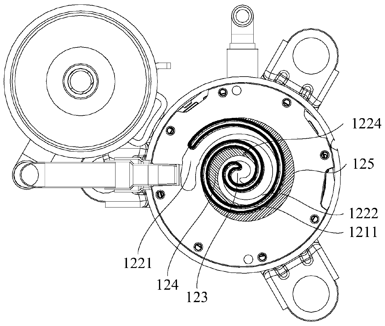
[0063] like figure 1 and figure 2 As shown, a scroll compressor 100 includes: a housing 110 with a suction port 111, a first exhaust port 112 and a second exhaust port 113; a compression assembly 120 including a moving disk 121 and The static disk 122 has a working chamber on the static disk 122, and the moving disk 121 separates the working chamber during the movement relative to the static disk 122 to form a first compression chamber 123 and a second compression chamber 124 that are independent of each other; wherein, the suction port 111 It communicates with the working chamber, the first compression chamber 123 communicates with the first exhaust port 112, the second compression chamber 124 communicates with the second exhaust port 113, and the first exhaust port 112 and the second exhaust port 113 are used to discharge different pressure gas.
[0064] The scroll compressor 100 provided by the present invention includes a casing 110 and a compression assembly 120, the c...
Embodiment 2
[0074] On the basis of the first embodiment above, as figure 1 and figure 2 As shown, it is further limited that the moving plate 121 separates the working chamber in the process of moving relative to the static plate 122, and also forms a first air suction chamber 125 and a second air suction chamber 126 that are independent of each other in sequence; the first air suction chamber 125 is formed by the second spiral The outer side wall of the part 1222 is surrounded by the helical groove 1221, and is located at the end of the second helical part 1222 at the outer periphery; the second suction chamber 126 is surrounded by the inner side wall of the second helical part 1222 and the helical groove 1221 formed, and located at the end of the second helical part 1222 on the outer periphery; during the rotation of the rotating disk 121, the first compression chamber 123 communicates with the first suction chamber 125, and the second compression chamber 124 communicates with the seco...
Embodiment 3
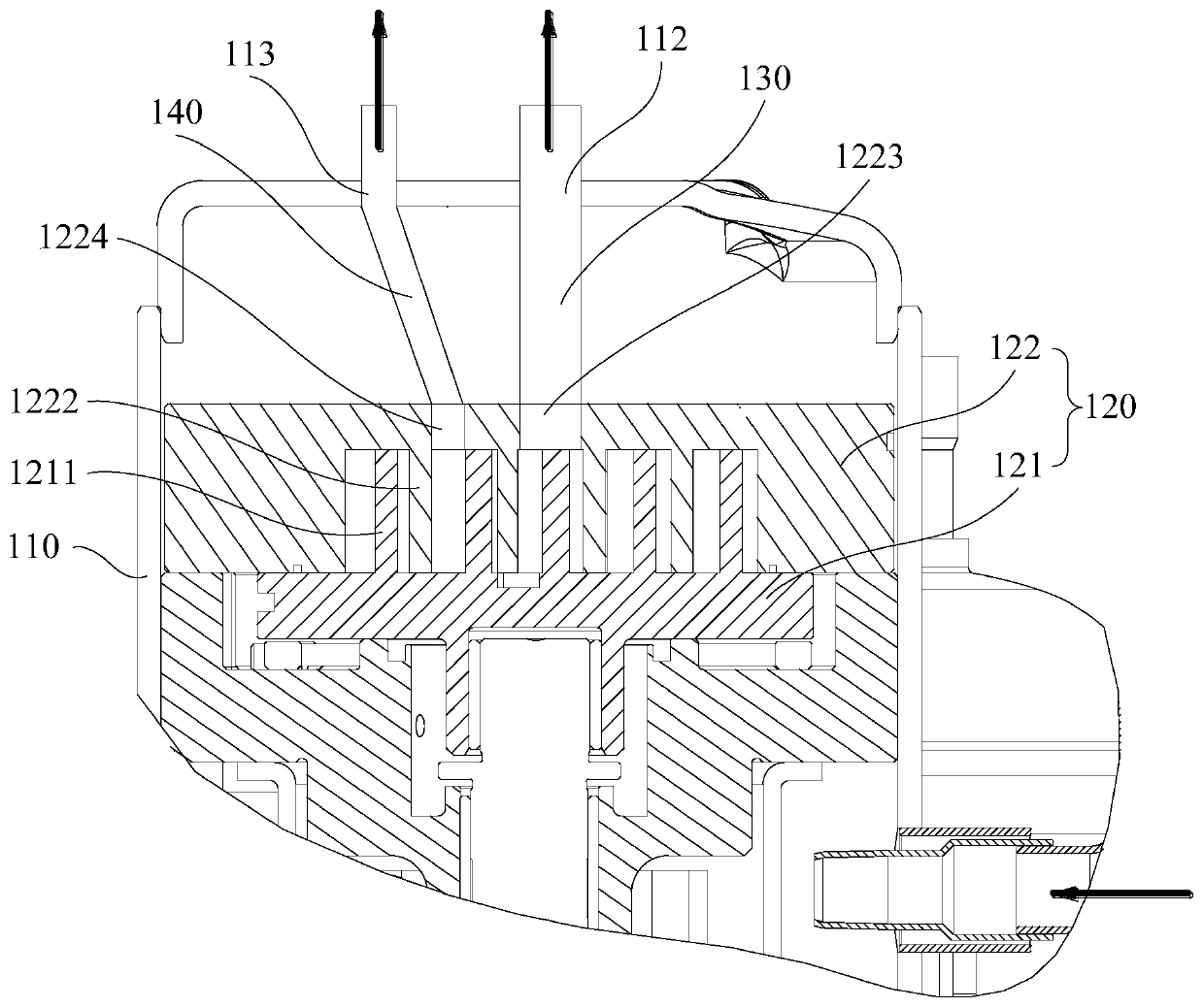
[0082] On the basis of any of the above-mentioned embodiments, such as image 3 As shown, the suction port 111 is further defined to communicate with the working chamber through the inner cavity of the casing 110; the scroll compressor 100 also includes a first exhaust passage 130 and a second exhaust passage 140 that are independent of each other, and the first compression chamber 123 communicates with the first exhaust port 112 through the first exhaust passage 130 , and the second compression chamber 124 communicates with the second exhaust port 113 through the second exhaust passage 140 .
[0083] In this embodiment, specifically, the suction port 111 is communicated with the working chamber through the inner cavity of the housing 110 so that the inner cavity of the housing 110 has a low back pressure structure. The first compression chamber 123 communicates with the first exhaust port 112 through the first exhaust passage 130 , and the second compression chamber 124 commu...
PUM
 Abstract
Description
Claims
Application Information
 - R&D Engineer
- R&D Manager
- IP Professional
- Industry Leading Data Capabilities
- Powerful AI technology
- Patent DNA Extraction
Browse by: Latest US Patents, China's latest patents, Technical Efficacy Thesaurus, Application Domain, Technology Topic.
© 2024 PatSnap. All rights reserved.Legal|Privacy policy|Modern Slavery Act Transparency Statement|Sitemap