Fixed point limiting type multistable reversing valve and work station switching method thereof

A multi-stable, directional valve technology, applied in the field of solenoid valves, can solve the problems of increasing the use cost of the solenoid directional valve and the power consumption of the electromagnet, and achieve the effects of simple structure, low cost and stable performance

Active Publication Date: 2020-06-19
杭州龚氏模具机械有限公司
View PDF4 Cites 0 Cited by
  • Summary
  • Abstract
  • Description
  • Claims
  • Application Information

AI Technical Summary

Problems solved by technology

[0002] In the existing electromagnetic reversing valve, there is only one stable working position that does not need to consume electric energy, but when the electromagnetic reversing valve is in an unstable working position, the electromagnet needs to be continuously energized to consume electric energy
This greatly improves the use cost of the electromagnetic reversing valve; among the existing electromagnetic valves, only the bistable electromagnetic energizing valve can have two stable working positions; however, for the reversing valve, it is often necessary to have three or three More than one working position to meet the requirements of use

Method used


Image

  • Fixed point limiting type multistable reversing valve and work station switching method thereof
  • Fixed point limiting type multistable reversing valve and work station switching method thereof
  • Fixed point limiting type multistable reversing valve and work station switching method thereof

Examples


Embodiment 1

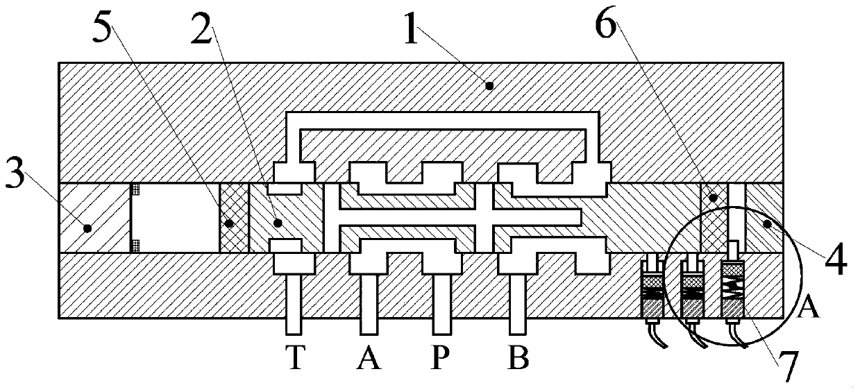
[0030] Such as figure 1 As shown, a fixed-point limiting multi-stable reversing valve includes a valve seat 1, a valve core 2, a first electromagnet 3, a second electromagnet 4, a moving permanent magnet 5, a moving suction block 6 and a fixed-point limiting bit agency7. Both the first electromagnet 3 and the second electromagnet 4 are de-energized electromagnets; the de-energized electromagnets have magnetism when no power is applied, and the magnetism disappears after being energized. The moving sucked block 6 adopts a magnetic material (a material that can be magnetized). The valve seat 1 is provided with a valve core placement channel. The first electromagnet 3 and the second electromagnet 4 are respectively fixed at both ends of the spool placement channel. The inner end of the first electromagnet 3 is provided with a buffer ring. The spool 2 is elongated and forms a sliding pair with the spool placement channel. The valve core 2 is located between the first electrom...

Embodiment 2

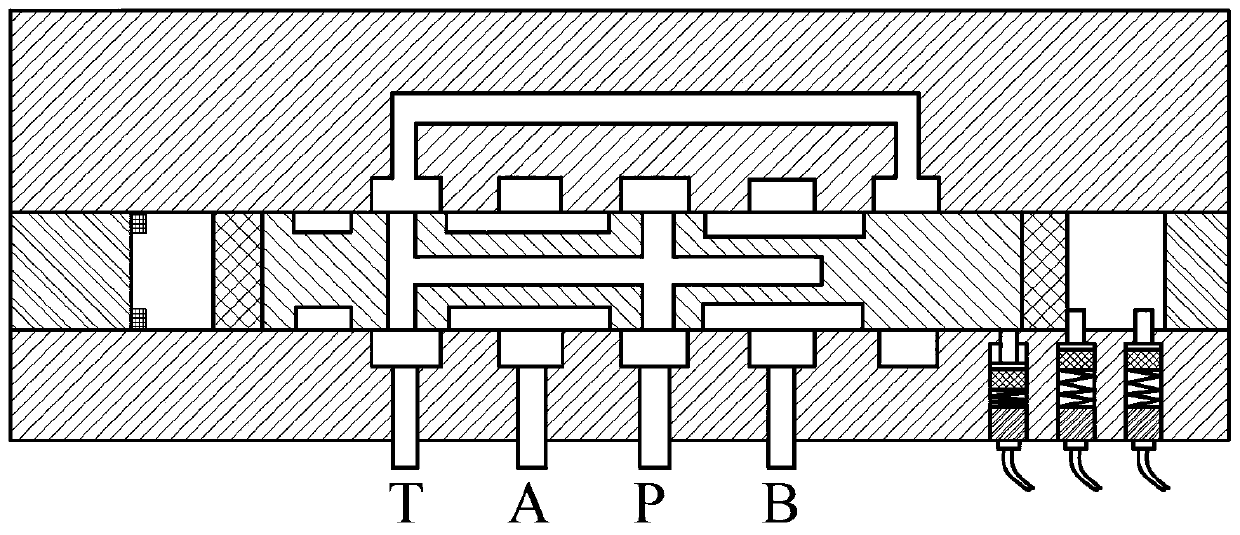
[0043] Such as Figure 5 As shown, a fixed-point limit multi-stable reversing valve includes a valve seat 1, a valve core 2, a first electromagnet 3, a moving suction block 6, a valve core positioning spring 8 and a fixed-point limit mechanism 7. The structures and relative positions of the valve seat 1, the valve core 2 and the fixed-point limit mechanism 7 are the same as those in the first embodiment.

[0044] The first electromagnet 3 is fixed at one end of the spool placement passage. The moving suction block 6 is fixed on the end of the valve core 2 facing the first electromagnet 3 . The first electromagnet 3 adopts an electrified type electromagnet, which generates a magnetic field when electrified, and generates suction to the moving suction block 6 . A valve core positioning spring 8 is arranged between the first electromagnet 3 and the moving sucked block 6 .

[0045] The working position switching method of the fixed-point limiting multi-stable reversing valve is...

Embodiment 3

[0047] A fixed-point limiting multi-stable reversing valve, the fixed-point limiting mechanism 7 in this embodiment is different from the fixed-point limiting mechanism 7 in Embodiment 1, and the rest are identical.

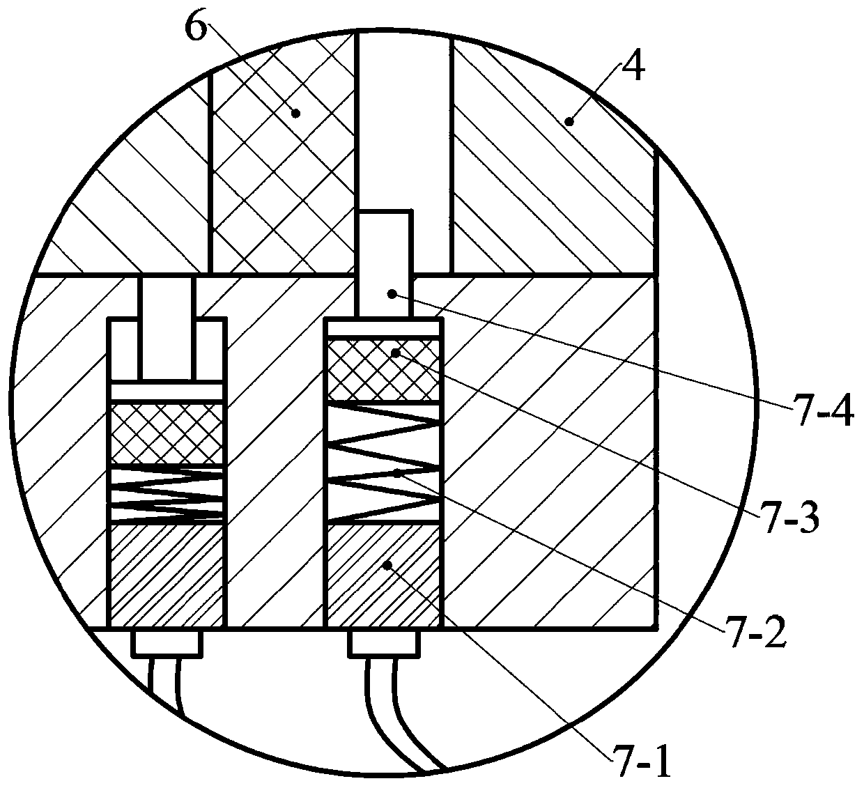
[0048] Such as Figure 6 As shown, the fixed-point limit mechanism 7 in this embodiment includes a limit electromagnet 7-1, a limit permanent magnet 7-5 and a limit block 7-4. The limit electromagnet 7-1, the limit permanent magnet 7-5, and the limit stopper 7-4 are arranged in the corresponding limit placement groove according to the order from outside to inside. The limit electromagnet 7-1 is fixed with the limit placement groove. The limit permanent magnet 7-5 is fixed with the inner end of the limit block 7-4. The limit block 7-4 forms a sliding pair with the limit placement groove. The inner end of the limit stopper 7-4 is stepped, corresponding to the step opening at the inner end of the limiter placement groove, forming a limit to the outer limit positi...


PUM


Abstract

The invention discloses a fixed point limiting type multistable reversing valve and a work station switching method thereof. In an existing electromagnet, only a double stable electromagnetic electrifying valve can have two stable work stations. The fixed point limiting type multistable reversing valve comprises a valve seat, a valve element, an electromagnetic driving assembly and fixed point limiting mechanisms. A valve element placing channel is formed in the valve seat. The valve element is arranged in the valve element placing channel. A plurality of oil ports are formed in the valve seat. The valve element is provided with m work stations in the valve seat. The valve element is driven by the electromagnetic driving assembly. m fixed point limiting mechanisms are arranged. By limitingthe valve element by means of the fixed point limiting mechanisms, the reversing valve in each work station does not consume electric energy and only needs to consume electric energy during switching, so that the use cost of the electromagnetic valve is lowered greatly. Furthermore, the defect that the electromagnetic valve in the existing electromagnetic electrifying valve is easy to damage as being electrified for a long time is overcome and the service life of the reversing valve is prolonged.

Description

technical field [0001] The invention belongs to the technical field of electromagnetic valves, and in particular relates to a fixed-point limit type multi-stable reversing valve and a working position switching method thereof. Background technique [0002] In the existing electromagnetic reversing valve, there is only one stable working position that does not need to consume electric energy, but when the electromagnetic reversing valve is in an unstable working position, the electromagnet needs to be continuously energized to consume electric energy. This greatly improves the use cost of the electromagnetic reversing valve; among the existing electromagnetic valves, only the bistable electromagnetic energizing valve can have two stable working positions; however, for the reversing valve, it is often necessary to have three or three more than one working position to meet the requirements of use. Therefore, it is very important to design a reversing valve in which all working...

Claims


Application Information

Patent Timeline
IPC IPC(8): F15B13/02F16K11/065F16K31/06
CPCF15B13/02F16K11/0655F16K31/061F16K31/0675
Inventor 王婧柴佳瑜倪虹叶霞勾治践蒋建海陈建华江霞
Owner 杭州龚氏模具机械有限公司
Why Eureka
Try Eureka