A power battery thermal management system based on the combination of two-stage heat pipe and vehicle body

A heat management system and power battery technology, applied in the direction of secondary batteries, circuits, electrical components, etc., to achieve the effects of compact system structure, improved heat exchange efficiency, and shortened heat exchange distance

Active Publication Date: 2022-06-07
CHINA UNIV OF MINING & TECH +1
View PDF5 Cites 0 Cited by
  • Summary
  • Abstract
  • Description
  • Claims
  • Application Information

AI Technical Summary

Problems solved by technology

Although the heat pipe, as an efficient heat transport medium, can quickly transport the heat absorbed from the battery to the outside of the battery system, the heat dissipation capacity of the condensing end is the bottleneck factor restricting the performance of the heat pipe cooling system.

Method used


Image

  • A power battery thermal management system based on the combination of two-stage heat pipe and vehicle body
  • A power battery thermal management system based on the combination of two-stage heat pipe and vehicle body
  • A power battery thermal management system based on the combination of two-stage heat pipe and vehicle body

Examples


Embodiment 1

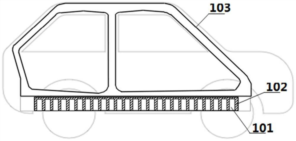
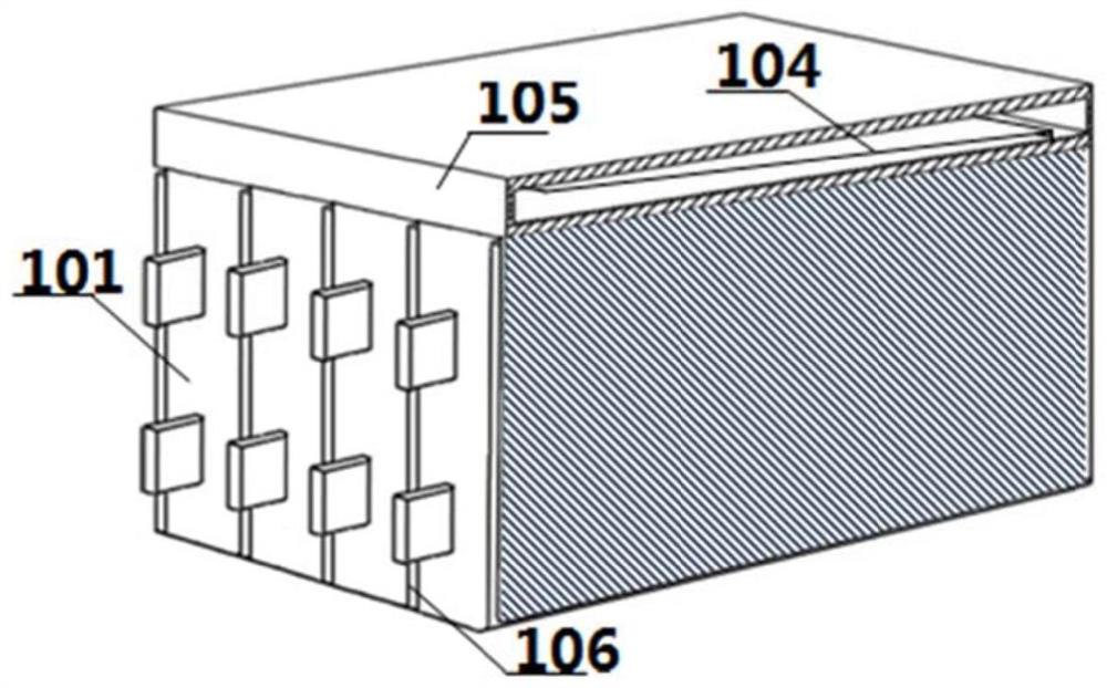
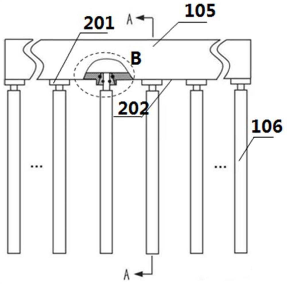
[0026] As shown in the figure, a power battery thermal management system based on the combination of two-stage heat pipes and a vehicle body includes several power battery cells 101, a three-dimensional ultra-thin heat pipe group 102 and a vehicle body heat pipe 103; the three-dimensional ultra-thin heat pipe group 102 is arranged on the vehicle body The bottom is composed of several ultra-thin evaporation plates 106 and a condenser 105; in order to enhance the detachability of the three-dimensional ultra-thin heat pipe group 102, the bottom surface 202 of the condenser 105 contains a tapered interface 201; the flexible joint of the ultra-thin evaporation plate 106 307 is connected with the tapered interface 201 through a sealing ring 305 and a self-clamping collar 306; the condenser 105 contains a gas-liquid splitter plate 104, and the gas-liquid splitter plate 104 separates the three-dimensional ultra-thin heat pipe group 102 into several parallel Complete circuit; the two su...

Embodiment 2

[0031] In this embodiment, the inner evaporation chamber of the ultra-thin evaporation plate 106 contains a micro-channel 501 structure with a stepped change in hydraulic diameter. The diameter of the micro-channel 501 gradually decreases in the direction away from the return channel 301 . Other implementations are the same as the first embodiment. .

Embodiment 3

[0033] In this embodiment, the inner evaporation chamber of the ultra-thin evaporation plate 106 contains a gradient porous structure 601 , and the average diameter of the pores gradually decreases in the direction away from the return channel 301 . Other implementations are the same as those in the first embodiment.


PUM


Abstract

The invention discloses a thermal management system for a power battery based on the combination of two-stage heat pipes and a vehicle body, including a three-dimensional ultra-thin heat pipe group and a body heat pipe. It contains a gas-liquid splitter plate, and its bottom surface has a tapered interface. The ultra-thin evaporation plate and the tapered interface are connected by a sealing ring and a self-carding collar. The power battery unit and the two ultra-thin evaporation plates of the three-dimensional ultra-thin heat pipe group Tight fit, the upper surface of the condenser and the bottom heat-absorbing cavity of the body heat pipe are closely bonded through high thermal conductivity materials, and the heat generated by the power battery can be quickly transferred to the roof of the car to dissipate heat to the environment through two-stage gas-liquid phase change heat transfer. The invention ingeniously integrates the power battery thermal management system with the body structure, increases the heat dissipation area, and can use the airflow during the movement of the car to dissipate heat. The invention has a simple structure, a compact battery pack, good temperature control performance, and has a broad market prospect.

Description

technical field [0001] The invention belongs to the field of power battery thermal management, in particular to a power battery thermal management system based on the combination of a two-stage heat pipe and a vehicle body. Background technique [0002] Energy shortage and environmental pollution have become problems faced by the development of today's world. The electric transformation and development of the automotive industry has great potential in the field of energy conservation and emission reduction. New energy electric vehicles occupy an important position in new energy vehicles due to their green and environmental advantages. The power of new energy electric vehicles comes from a battery pack composed of multiple single power batteries. During the charging and discharging process of the power battery, heat is generated due to the incomplete conversion of energy. If the heat dissipation is not timely, the local temperature of the battery will rise rapidly, affecting...

Claims


Application Information

Patent Timeline
Patent Type & Authority Patents(China)
IPC IPC(8): H01M10/613H01M10/625H01M10/6552H01M10/6569
CPCH01M10/613H01M10/625H01M10/6552H01M10/6569Y02E60/10
Inventor 赵佳腾姜威饶中浩周寿斌姜庆海吴战宇
Owner CHINA UNIV OF MINING & TECH
Why Eureka
Try Eureka